Volume → rows → covered footprint

Supported in the planning workbench

How much covered ground does your stacked wood and access need?

Firewood planning starts with the task you need to complete. Compare the disclosed examples below, then replace their assumptions with your measurements and keep your decision in one supplier brief.

Reference answer: 1 cord of stacked wood uses 1 row at 48 in high, 24 in deep, plus 24 in access aisles. The smallest passing footprint in this three-candidate example is 16×8. This answers the disclosed example, not an unmeasured personal project.

Compare reference arrangements

Authored planning examples, not measured customer projects or product specifications. Dimensions are inches. No construction or safety approval.

Measure the conditions that change the answer.

Stacked volume

How to measure: Enter stacked cords, not loose truck-bed volume. One cord is 128 cubic feet including the spaces within the stack.

What it changes: Volume changes every row's required length; access aisles never increase capacity.

Height, depth and rows

How to measure: Measure the intended stack height and one row's depth; enter a whole row count. Do not substitute the roof height for stack height.

What it changes: The same volume can need a long single row or a deeper multi-row footprint.

Open sides and access

How to measure: Enter the actual aisle width and whether access is needed behind the final row. Check the cover edge and open row ends on site.

What it changes: A cover-boundary failure needs a different arrangement or footprint. Rain exposure, air movement and stack stability remain separate checks.

Two ways to frame the decision.

Reference 1 · editable assumptions

Long single row

What you gain
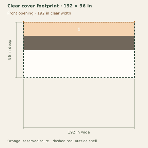
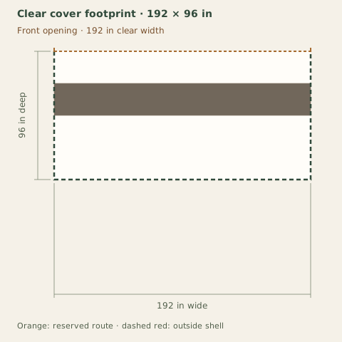
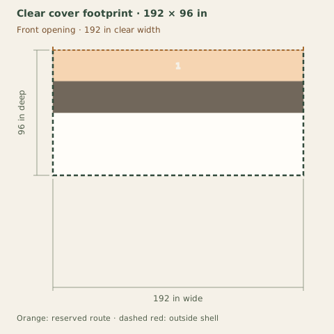
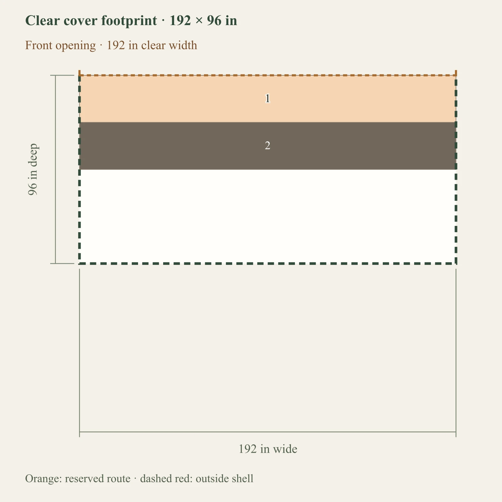
One continuous row keeps the example shallow: 192 inches of row length plus a separate front aisle.
What you give up
It needs a long open-ended cover; dividing volume into more rows changes depth rather than volume.
When to choose it
Use this direction when a long boundary is available and you want direct access to one row.
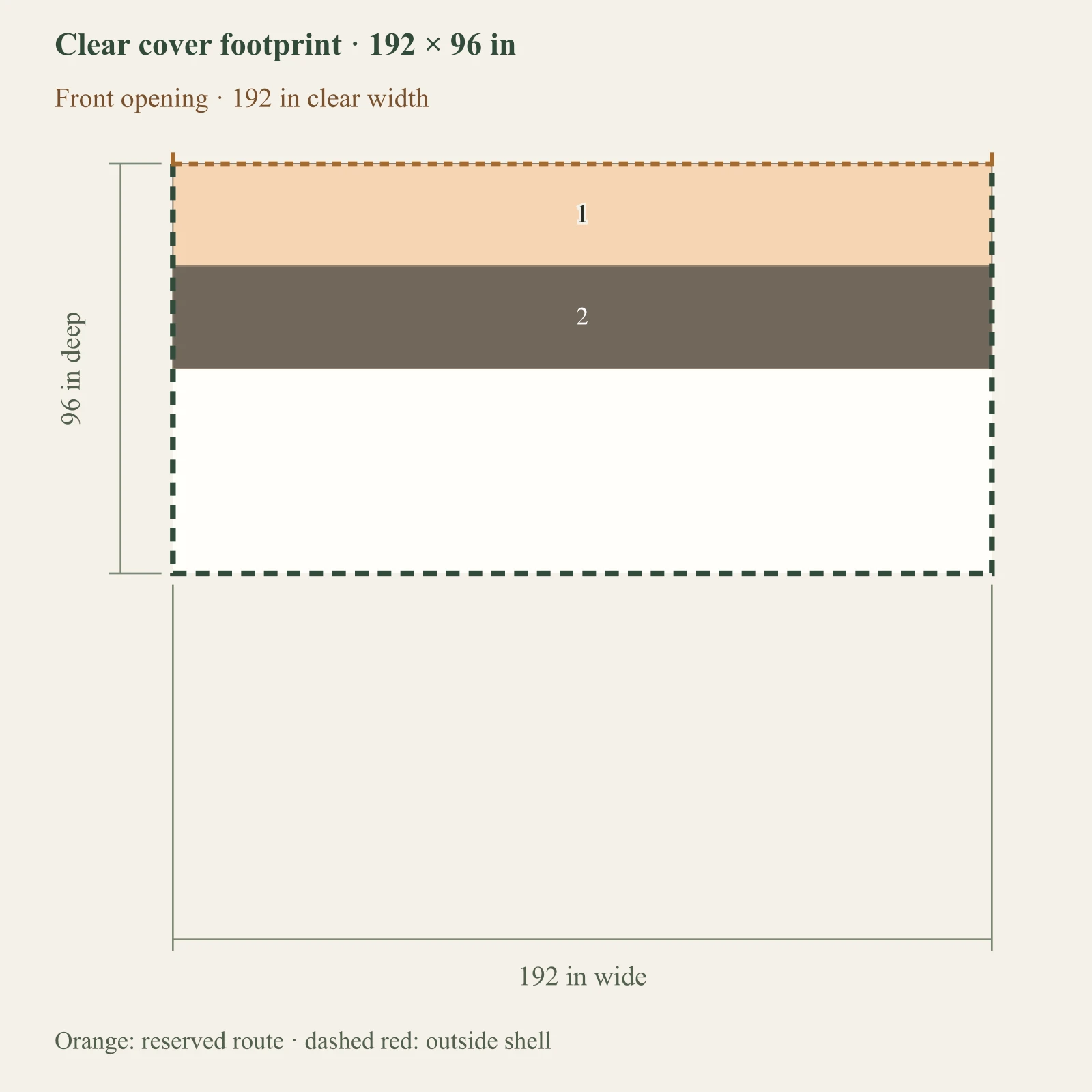
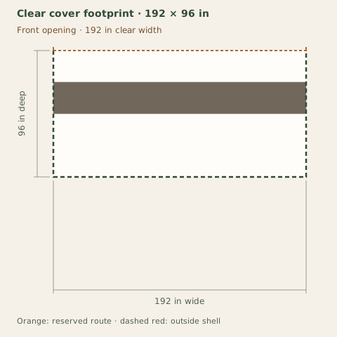
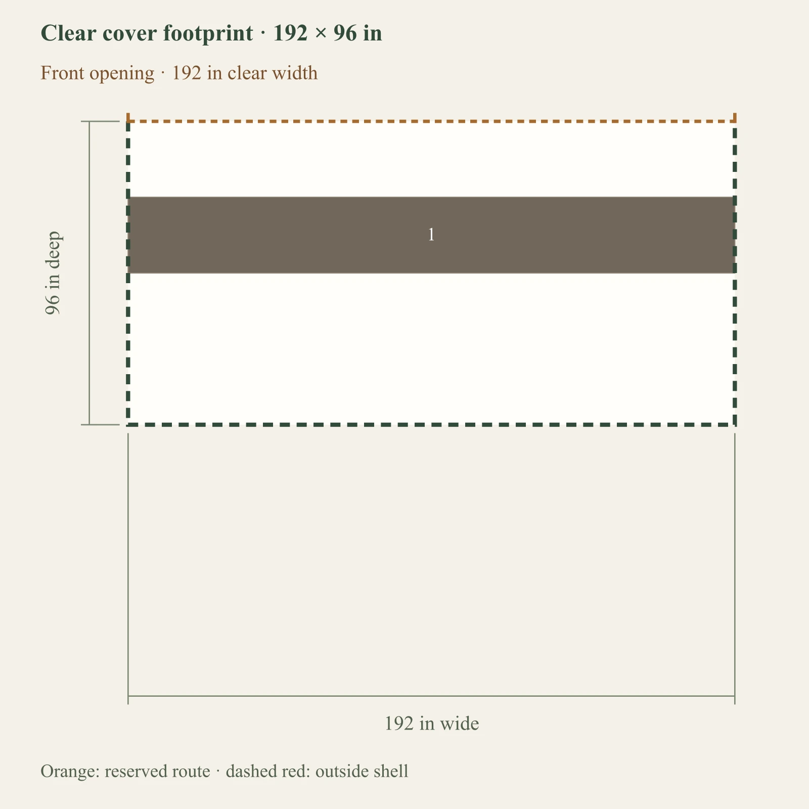
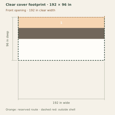
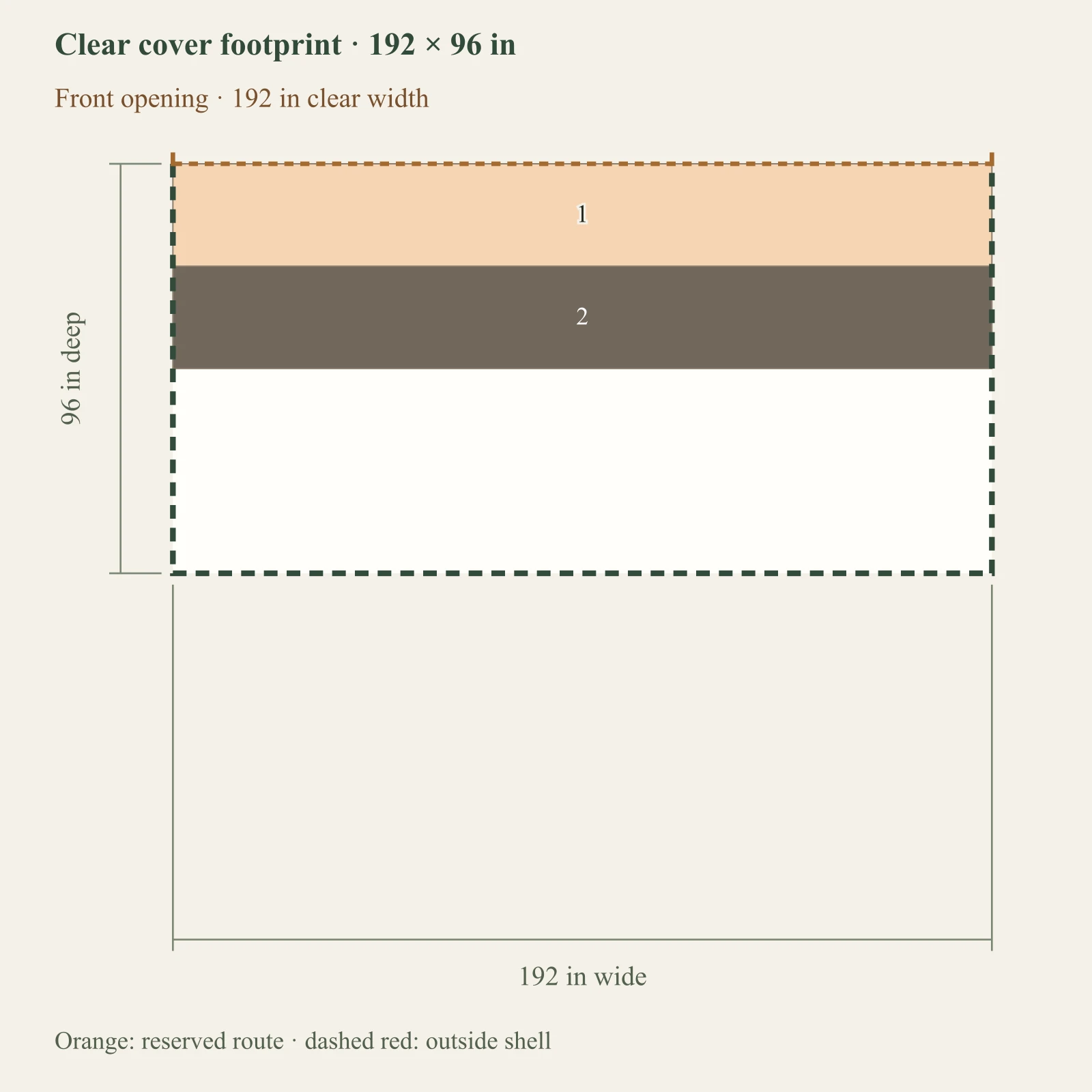
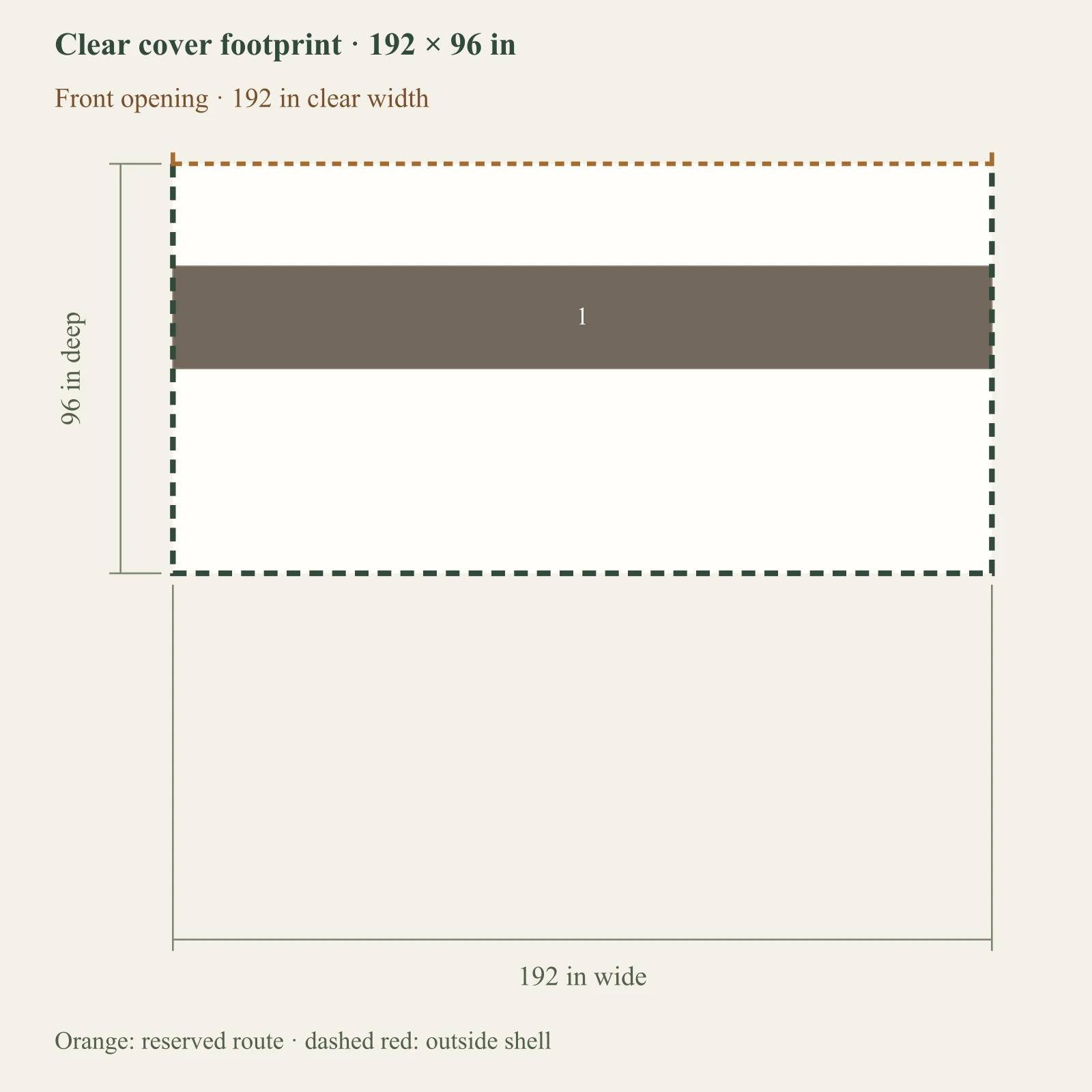
Full-size layout and reserved spaces1 cord(s), 48 in stack height, 24 in row depth. Aisles are entered assumptions. Open-end cover concept; not a roof or airflow design. Objects outside the outlined shell have not been placed. Numbers refer to the object list. This is a planning diagram, not a construction drawing.Access aisle 1: 192 × 24 in at 0, 0 inWood row 1: 192 × 24 in at 0, 24 in12Clear cover footprint · 192 × 96 inFront opening · 192 in clear width192 in wide96 in deepOrange: reserved route · dashed red: outside shell

Dark: equipment or storage. Pale areas: activities or zones. Dimensions in inches; scale changes with the view.

  1. 1. Access aisle 1: 192 × 24 in
  2. 2. Wood row 1: 192 × 24 in

Inspect the layout

100%

Dimensions in inches. Zoom changes the view, not your measurements. Select an object to identify its footprint, then swipe or scroll within the drawing. With a keyboard, focus the drawing and use arrow keys.

Input-based planning only. Turning, ramps, thresholds, wall mounting and structural capacity are not approved by this diagram. Escape or Close returns to the page.

The stated geometry fits this arrangement.

128 cubic feet of stacked volume; 192 in per row. Aisles contain no wood volume.

Every input, finding and limitation
  • cords: 1
  • stack Height: 48
  • row Depth: 24
  • rows: 1
  • access Sides: one
  • aisle: 24
  • use: ready-use
  • 128 cubic feet of stacked volume; 192 in per row. Aisles contain no wood volume.
  • 1 rows: 192 in wide × 48 in deep including the entered aisles. Wood-only floor area stays 32 sq ft.
  • 2 rows: 96 in wide × 96 in deep including the entered aisles. Wood-only floor area stays 32 sq ft.
  • 3 rows: 64 in wide × 144 in deep including the entered aisles. Wood-only floor area stays 32 sq ft.
  • Rows are accessed from their open ends. Confirm actual open sides and obstructions; a closed storage shell is not this cover model.
  • Rain protection, airflow, seasoning time and stack stability are not evaluated. NIST supports volume conversion only.

Reference 2 · editable assumptions

Shorter multiple rows

What you gain
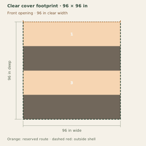
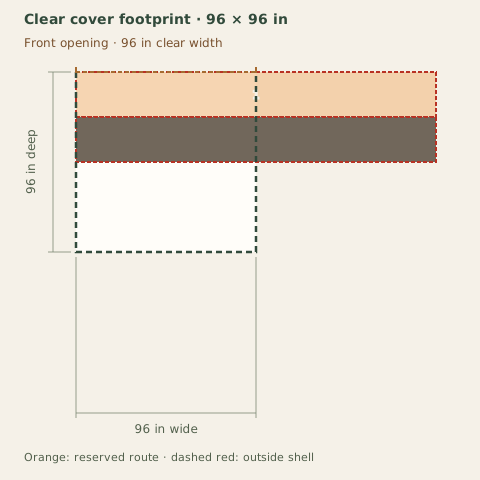
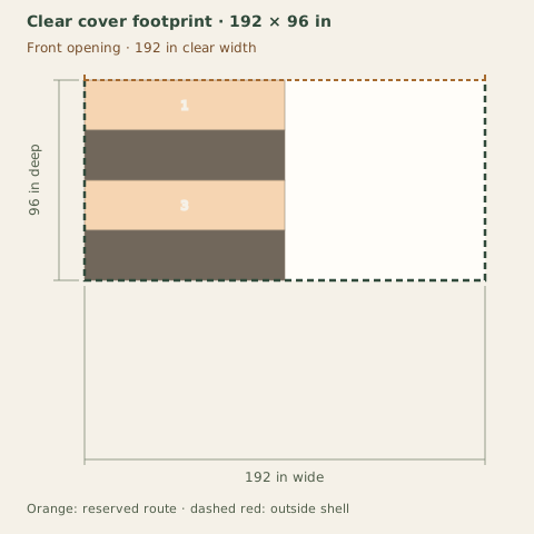
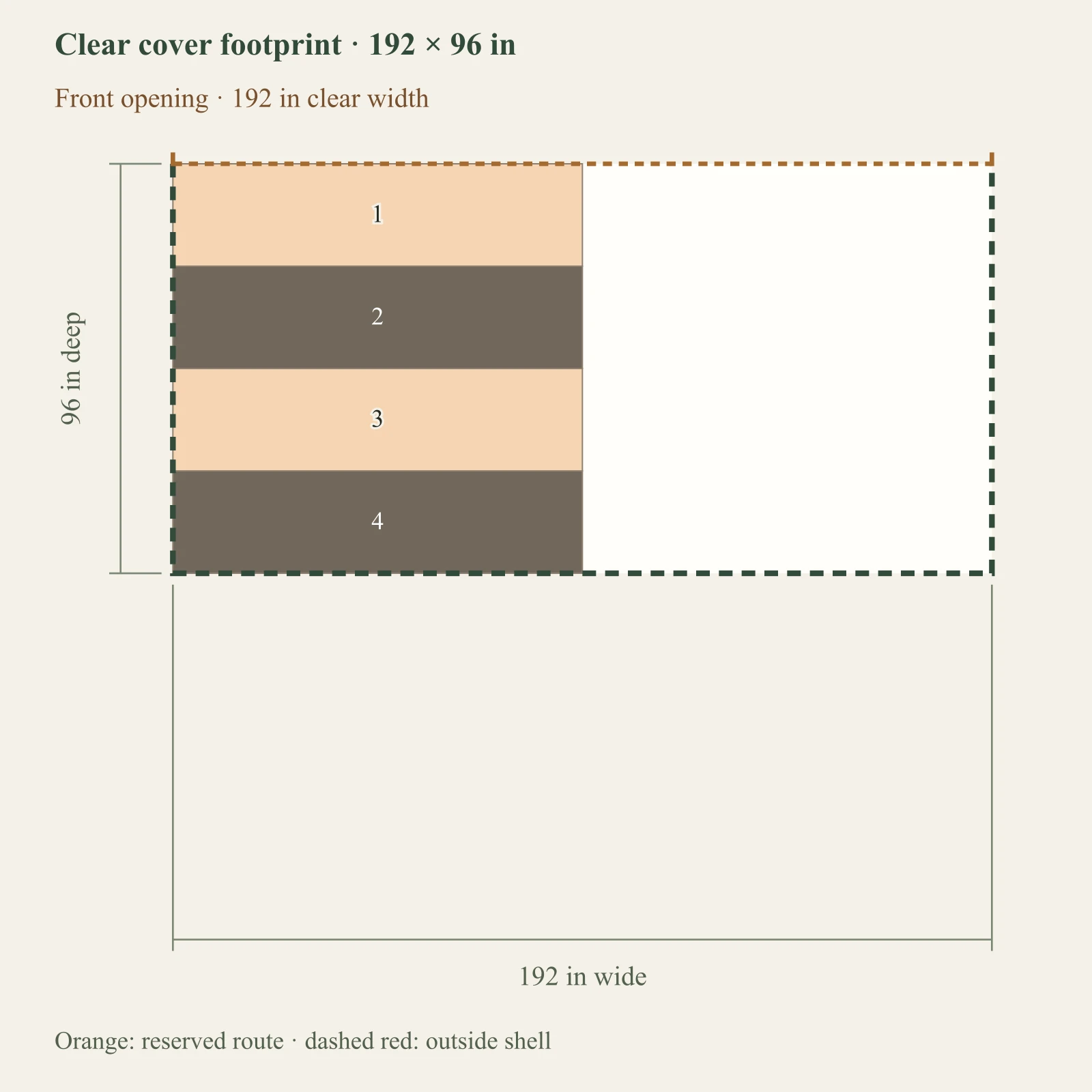
Two 96-inch rows shorten the same one-cord example.
What you give up
The second row and its access aisle consume additional depth. Two-sided access adds another aisle.
When to choose it
Use this direction when width is limited and you can retain access to each row.
Full-size layout and reserved spaces1 cord(s), 48 in stack height, 24 in row depth. Aisles are entered assumptions. Open-end cover concept; not a roof or airflow design. Objects outside the outlined shell have not been placed. Numbers refer to the object list. This is a planning diagram, not a construction drawing.Access aisle 1: 96 × 24 in at 0, 0 inWood row 1: 96 × 24 in at 0, 24 inAccess aisle 2: 96 × 24 in at 0, 48 inWood row 2: 96 × 24 in at 0, 72 in1234Clear cover footprint · 96 × 96 inFront opening · 96 in clear width96 in wide96 in deepOrange: reserved route · dashed red: outside shell

Dark: equipment or storage. Pale areas: activities or zones. Dimensions in inches; scale changes with the view.

  1. 1. Access aisle 1: 96 × 24 in
  2. 2. Wood row 1: 96 × 24 in
  3. 3. Access aisle 2: 96 × 24 in
  4. 4. Wood row 2: 96 × 24 in

Inspect the layout

100%

Dimensions in inches. Zoom changes the view, not your measurements. Select an object to identify its footprint, then swipe or scroll within the drawing. With a keyboard, focus the drawing and use arrow keys.

Input-based planning only. Turning, ramps, thresholds, wall mounting and structural capacity are not approved by this diagram. Escape or Close returns to the page.

The stated geometry fits this arrangement.

128 cubic feet of stacked volume; 96 in per row. Aisles contain no wood volume.

Every input, finding and limitation
  • cords: 1
  • stack Height: 48
  • row Depth: 24
  • rows: 2
  • access Sides: one
  • aisle: 24
  • use: ready-use
  • 128 cubic feet of stacked volume; 96 in per row. Aisles contain no wood volume.
  • 1 rows: 192 in wide × 48 in deep including the entered aisles. Wood-only floor area stays 32 sq ft.
  • 2 rows: 96 in wide × 96 in deep including the entered aisles. Wood-only floor area stays 32 sq ft.
  • 3 rows: 64 in wide × 144 in deep including the entered aisles. Wood-only floor area stays 32 sq ft.
  • Rows are accessed from their open ends. Confirm actual open sides and obstructions; a closed storage shell is not this cover model.
  • Rain protection, airflow, seasoning time and stack stability are not evaluated. NIST supports volume conversion only.

Same task, three candidate footprints.

Reference 1 stays fixed. These are authored clear dimensions, not guaranteed interiors of products bearing the same nominal size. Each diagram uses the same scale; failed objects remain full size.

At least one shown arrangement passes the modeled geometry; read the remaining limits before making a choice.

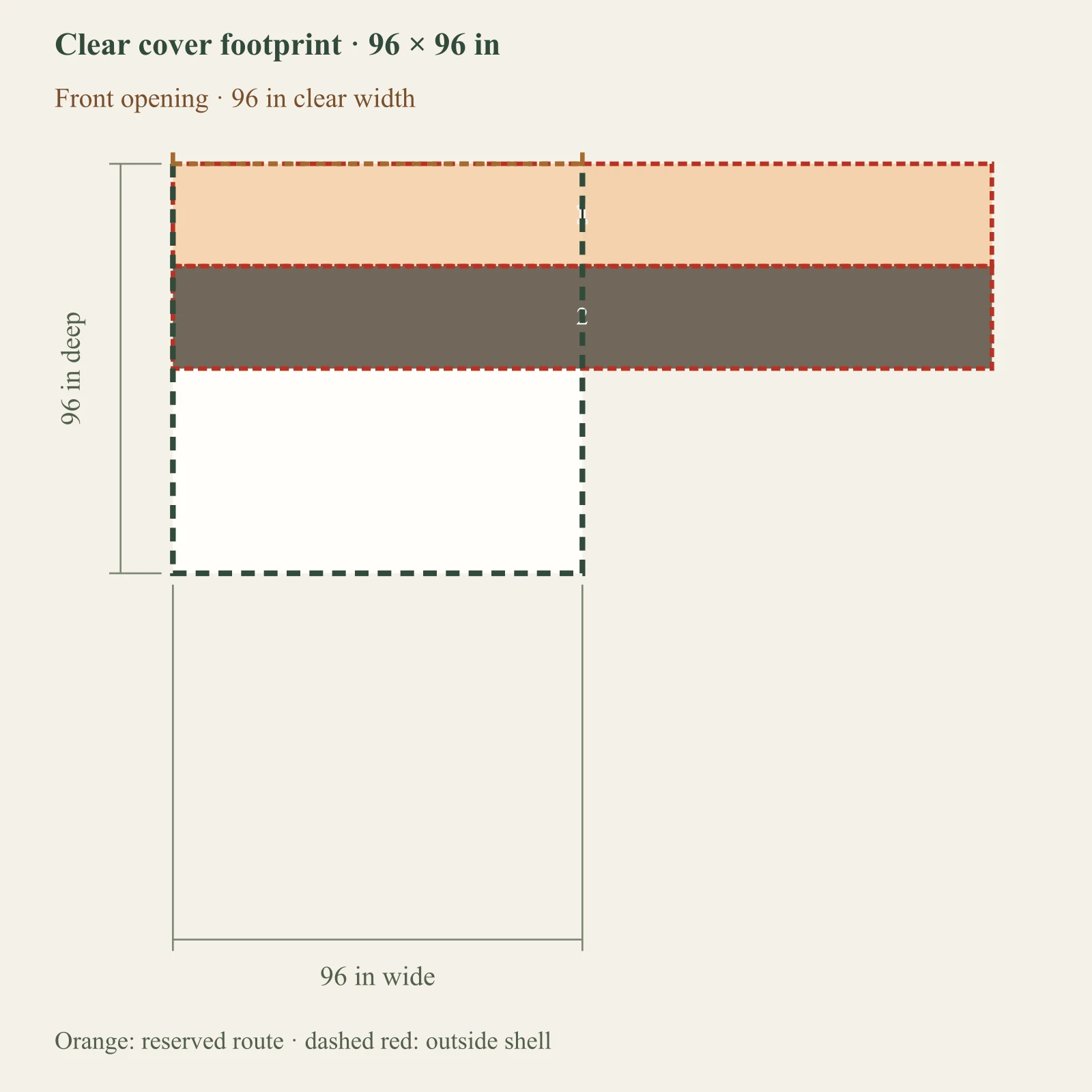
8×8

Full-size layout and reserved spaces1 cord(s), 48 in stack height, 24 in row depth. Aisles are entered assumptions. Open-end cover concept; not a roof or airflow design. Objects outside the outlined shell have not been placed. Numbers refer to the object list. This is a planning diagram, not a construction drawing.Access aisle 1: 192 × 24 in at 0, 0 inWood row 1: 192 × 24 in at 0, 24 in12Clear cover footprint · 96 × 96 inFront opening · 96 in clear width96 in wide96 in deepOrange: reserved route · dashed red: outside shell

Dark: equipment or storage. Pale areas: activities or zones. Dimensions in inches; scale changes with the view.

  1. 1. Access aisle 1: 192 × 24 in — outside shell
  2. 2. Wood row 1: 192 × 24 in — outside shell

Inspect the layout

100%

Dimensions in inches. Zoom changes the view, not your measurements. Select an object to identify its footprint, then swipe or scroll within the drawing. With a keyboard, focus the drawing and use arrow keys.

Input-based planning only. Turning, ramps, thresholds, wall mounting and structural capacity are not approved by this diagram. Escape or Close returns to the page.

This arrangement needs a change.

Access aisle 1 extends beyond the cover footprint.

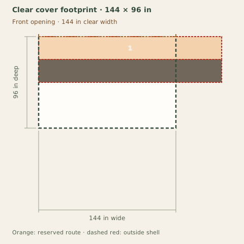
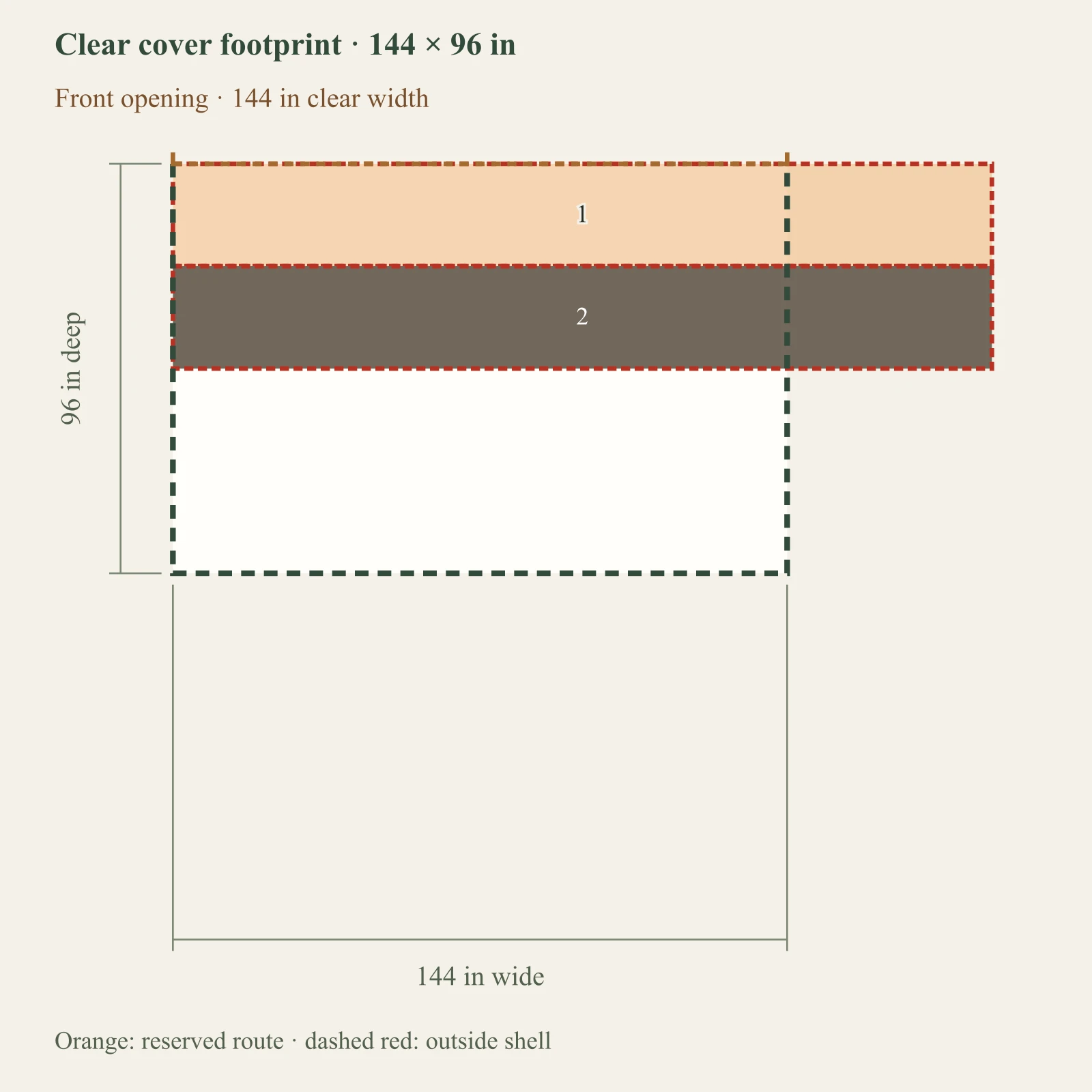
12×8

Full-size layout and reserved spaces1 cord(s), 48 in stack height, 24 in row depth. Aisles are entered assumptions. Open-end cover concept; not a roof or airflow design. Objects outside the outlined shell have not been placed. Numbers refer to the object list. This is a planning diagram, not a construction drawing.Access aisle 1: 192 × 24 in at 0, 0 inWood row 1: 192 × 24 in at 0, 24 in12Clear cover footprint · 144 × 96 inFront opening · 144 in clear width144 in wide96 in deepOrange: reserved route · dashed red: outside shell

Dark: equipment or storage. Pale areas: activities or zones. Dimensions in inches; scale changes with the view.

  1. 1. Access aisle 1: 192 × 24 in — outside shell
  2. 2. Wood row 1: 192 × 24 in — outside shell

Inspect the layout

100%

Dimensions in inches. Zoom changes the view, not your measurements. Select an object to identify its footprint, then swipe or scroll within the drawing. With a keyboard, focus the drawing and use arrow keys.

Input-based planning only. Turning, ramps, thresholds, wall mounting and structural capacity are not approved by this diagram. Escape or Close returns to the page.

This arrangement needs a change.

Access aisle 1 extends beyond the cover footprint.

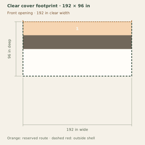
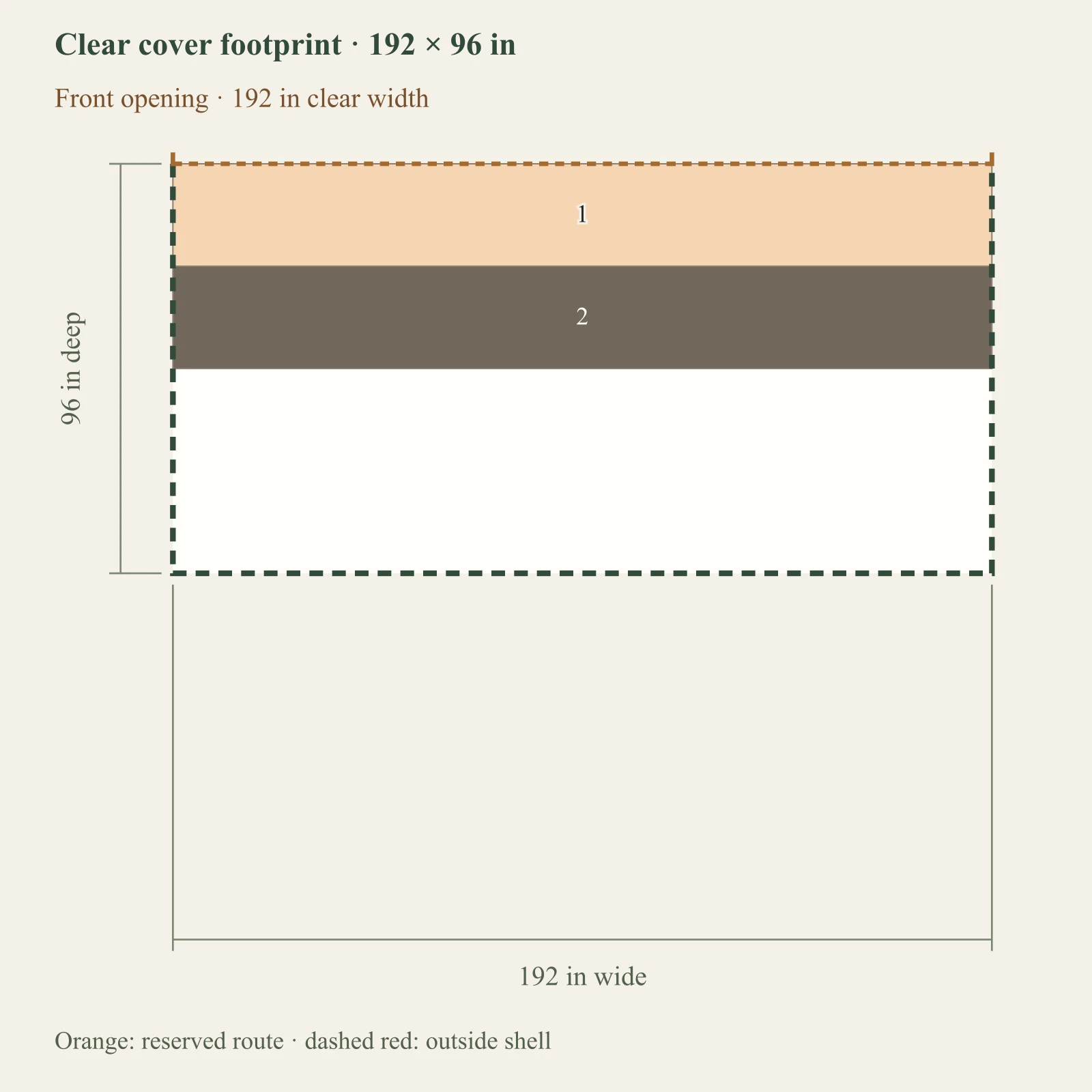
16×8

Full-size layout and reserved spaces1 cord(s), 48 in stack height, 24 in row depth. Aisles are entered assumptions. Open-end cover concept; not a roof or airflow design. Objects outside the outlined shell have not been placed. Numbers refer to the object list. This is a planning diagram, not a construction drawing.Access aisle 1: 192 × 24 in at 0, 0 inWood row 1: 192 × 24 in at 0, 24 in12Clear cover footprint · 192 × 96 inFront opening · 192 in clear width192 in wide96 in deepOrange: reserved route · dashed red: outside shell

Dark: equipment or storage. Pale areas: activities or zones. Dimensions in inches; scale changes with the view.

  1. 1. Access aisle 1: 192 × 24 in
  2. 2. Wood row 1: 192 × 24 in

Inspect the layout

100%

Dimensions in inches. Zoom changes the view, not your measurements. Select an object to identify its footprint, then swipe or scroll within the drawing. With a keyboard, focus the drawing and use arrow keys.

Input-based planning only. Turning, ramps, thresholds, wall mounting and structural capacity are not approved by this diagram. Escape or Close returns to the page.

The stated geometry fits this arrangement.

128 cubic feet of stacked volume; 192 in per row. Aisles contain no wood volume.

One cord, three row arrangements.

Height stays 48 inches and row depth stays 24 inches. Every arrangement holds 128 cubic feet of stacked volume; the 24-inch example aisles are additional ground space. A covered footprint does not establish rain protection, airflow or a drying time.

1 row(s)

Full-size layout and reserved spaces1 cord(s), 48 in stack height, 24 in row depth. Aisles are entered assumptions. Open-end cover concept; not a roof or airflow design. Objects outside the outlined shell have not been placed. Numbers refer to the object list. This is a planning diagram, not a construction drawing.Access aisle 1: 192 × 24 in at 0, 0 inWood row 1: 192 × 24 in at 0, 24 in12Clear cover footprint · 192 × 96 inFront opening · 192 in clear width192 in wide96 in deepOrange: reserved route · dashed red: outside shell

Dark: equipment or storage. Pale areas: activities or zones. Dimensions in inches; scale changes with the view.

  1. 1. Access aisle 1: 192 × 24 in
  2. 2. Wood row 1: 192 × 24 in

128 cubic feet of stacked volume; 192 in per row. Aisles contain no wood volume.

2 row(s)

Full-size layout and reserved spaces1 cord(s), 48 in stack height, 24 in row depth. Aisles are entered assumptions. Open-end cover concept; not a roof or airflow design. Objects outside the outlined shell have not been placed. Numbers refer to the object list. This is a planning diagram, not a construction drawing.Access aisle 1: 96 × 24 in at 0, 0 inWood row 1: 96 × 24 in at 0, 24 inAccess aisle 2: 96 × 24 in at 0, 48 inWood row 2: 96 × 24 in at 0, 72 in1234Clear cover footprint · 192 × 96 inFront opening · 192 in clear width192 in wide96 in deepOrange: reserved route · dashed red: outside shell

Dark: equipment or storage. Pale areas: activities or zones. Dimensions in inches; scale changes with the view.

  1. 1. Access aisle 1: 96 × 24 in
  2. 2. Wood row 1: 96 × 24 in
  3. 3. Access aisle 2: 96 × 24 in
  4. 4. Wood row 2: 96 × 24 in

128 cubic feet of stacked volume; 96 in per row. Aisles contain no wood volume.

3 row(s)

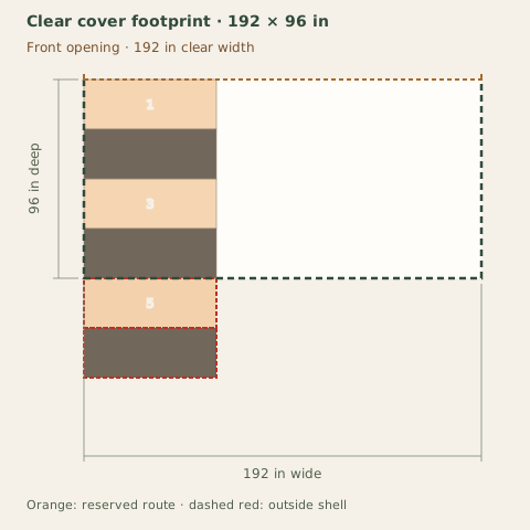
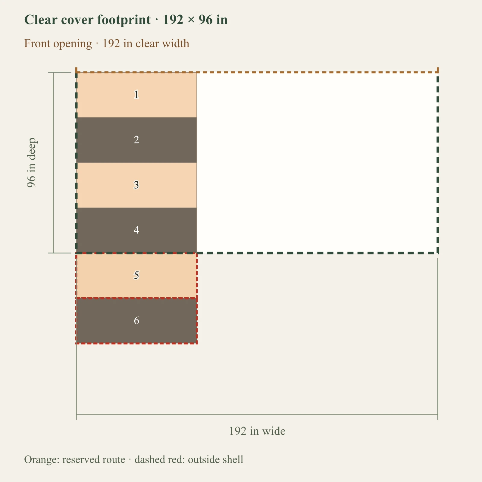
Full-size layout and reserved spaces1 cord(s), 48 in stack height, 24 in row depth. Aisles are entered assumptions. Open-end cover concept; not a roof or airflow design. Objects outside the outlined shell have not been placed. Numbers refer to the object list. This is a planning diagram, not a construction drawing.Access aisle 1: 64 × 24 in at 0, 0 inWood row 1: 64 × 24 in at 0, 24 inAccess aisle 2: 64 × 24 in at 0, 48 inWood row 2: 64 × 24 in at 0, 72 inAccess aisle 3: 64 × 24 in at 0, 96 inWood row 3: 64 × 24 in at 0, 120 in123456Clear cover footprint · 192 × 96 inFront opening · 192 in clear width192 in wide96 in deepOrange: reserved route · dashed red: outside shell

Dark: equipment or storage. Pale areas: activities or zones. Dimensions in inches; scale changes with the view.

  1. 1. Access aisle 1: 64 × 24 in
  2. 2. Wood row 1: 64 × 24 in
  3. 3. Access aisle 2: 64 × 24 in
  4. 4. Wood row 2: 64 × 24 in
  5. 5. Access aisle 3: 64 × 24 in — outside shell
  6. 6. Wood row 3: 64 × 24 in — outside shell

Access aisle 3 extends beyond the cover footprint.

Test the task in use.

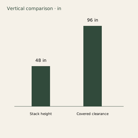
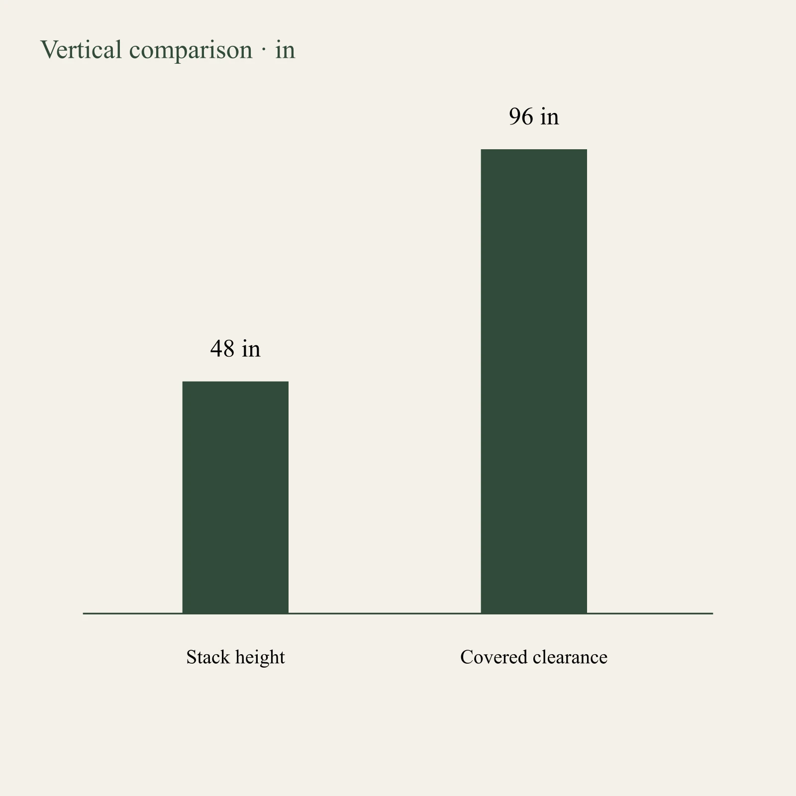
Stack height below the entered cover clearance

Vertical comparison · in48 inStack height96 inCovered clearance
Stack height below the entered cover clearance. Stack height: 48 in; Covered clearance: 96 in. Entered heights fit this comparison. No opening motion or structural check is inferred.

Inspect the layout

100%

Dimensions in inches. Zoom changes the view, not your measurements. Select an object to identify its footprint, then swipe or scroll within the drawing. With a keyboard, focus the drawing and use arrow keys.

Input-based planning only. Turning, ramps, thresholds, wall mounting and structural capacity are not approved by this diagram. Escape or Close returns to the page.

Wood footprint only — excludes access area

Wood footprint only — excludes access area1 cord(s), 48 in stack height, 24 in row depth. Aisles are entered assumptions. Open-end cover concept; not a roof or airflow design. Objects outside the outlined shell have not been placed. Numbers refer to the object list. This is a planning diagram, not a construction drawing.Wood row 1: 192 × 24 in at 0, 24 in1Clear cover footprint · 192 × 96 inFront opening · 192 in clear width192 in wide96 in deepOrange: reserved route · dashed red: outside shell

Dark: equipment or storage. Pale areas: activities or zones. Dimensions in inches; scale changes with the view.

  1. 1. Wood row 1: 192 × 24 in

Inspect the layout

100%

Dimensions in inches. Zoom changes the view, not your measurements. Select an object to identify its footprint, then swipe or scroll within the drawing. With a keyboard, focus the drawing and use arrow keys.

Input-based planning only. Turning, ramps, thresholds, wall mounting and structural capacity are not approved by this diagram. Escape or Close returns to the page.

Separate access aisles — no added wood capacity

Separate access aisles — no added wood capacity1 cord(s), 48 in stack height, 24 in row depth. Aisles are entered assumptions. Open-end cover concept; not a roof or airflow design. Objects outside the outlined shell have not been placed. Numbers refer to the object list. This is a planning diagram, not a construction drawing.Access aisle 1: 192 × 24 in at 0, 0 inWood row 1: 192 × 24 in at 0, 24 in12Clear cover footprint · 192 × 96 inFront opening · 192 in clear width192 in wide96 in deepOrange: reserved route · dashed red: outside shell

Dark: equipment or storage. Pale areas: activities or zones. Dimensions in inches; scale changes with the view.

  1. 1. Access aisle 1: 192 × 24 in
  2. 2. Wood row 1: 192 × 24 in

Inspect the layout

100%

Dimensions in inches. Zoom changes the view, not your measurements. Select an object to identify its footprint, then swipe or scroll within the drawing. With a keyboard, focus the drawing and use arrow keys.

Input-based planning only. Turning, ramps, thresholds, wall mounting and structural capacity are not approved by this diagram. Escape or Close returns to the page.

Cover edges and open rows — verify rain exposure and air movement on site

Cover edges and open rows — verify rain exposure and air movement on site1 cord(s), 48 in stack height, 24 in row depth. Aisles are entered assumptions. Open-end cover concept; not a roof or airflow design. Objects outside the outlined shell have not been placed. Numbers refer to the object list. This is a planning diagram, not a construction drawing.Wood row 1: 192 × 24 in at 0, 24 in1Clear cover footprint · 192 × 96 inFront opening · 192 in clear width192 in wide96 in deepOrange: reserved route · dashed red: outside shell

Dark: equipment or storage. Pale areas: activities or zones. Dimensions in inches; scale changes with the view.

  1. 1. Wood row 1: 192 × 24 in

Inspect the layout

100%

Dimensions in inches. Zoom changes the view, not your measurements. Select an object to identify its footprint, then swipe or scroll within the drawing. With a keyboard, focus the drawing and use arrow keys.

Input-based planning only. Turning, ramps, thresholds, wall mounting and structural capacity are not approved by this diagram. Escape or Close returns to the page.

Controlled failure

What changes the answer?

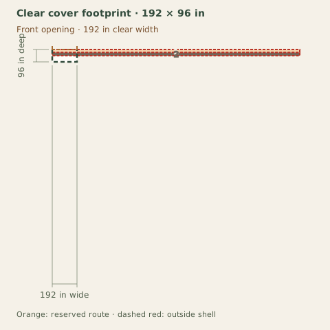
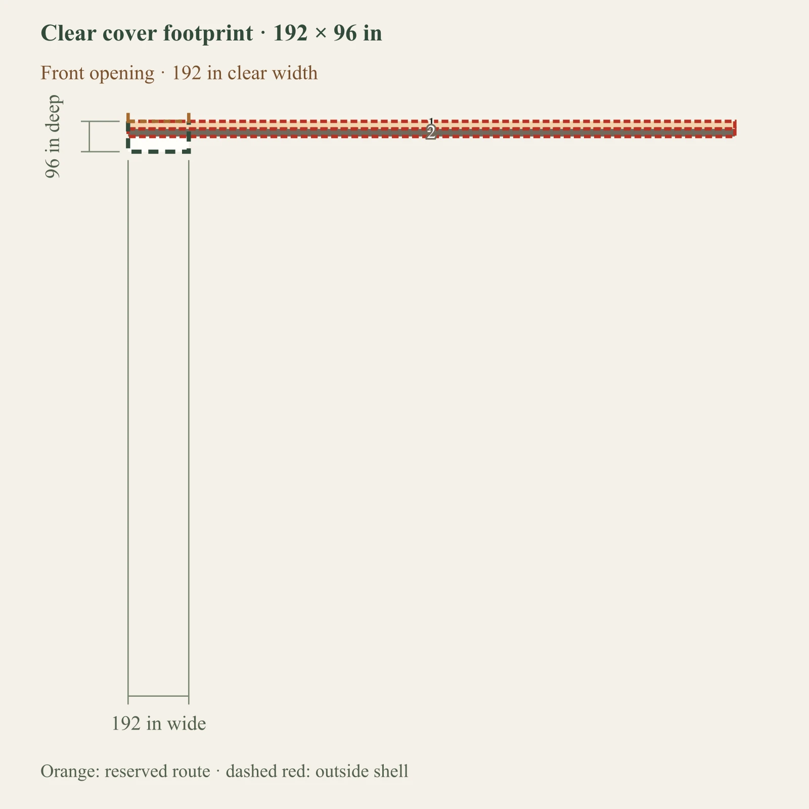
Increase only stored volume to 10 cords.

  • Access aisle 1 extends beyond the cover footprint.
  • Wood row 1 extends beyond the cover footprint.
Full-size layout and reserved spaces10 cord(s), 48 in stack height, 24 in row depth. Aisles are entered assumptions. Open-end cover concept; not a roof or airflow design. Objects outside the outlined shell have not been placed. Numbers refer to the object list. This is a planning diagram, not a construction drawing.Access aisle 1: 1920 × 24 in at 0, 0 inWood row 1: 1920 × 24 in at 0, 24 in12Clear cover footprint · 192 × 96 inFront opening · 192 in clear width192 in wide96 in deepOrange: reserved route · dashed red: outside shell

Dark: equipment or storage. Pale areas: activities or zones. Dimensions in inches; scale changes with the view.

  1. 1. Access aisle 1: 1920 × 24 in — outside shell
  2. 2. Wood row 1: 1920 × 24 in — outside shell

Inspect the layout

100%

Dimensions in inches. Zoom changes the view, not your measurements. Select an object to identify its footprint, then swipe or scroll within the drawing. With a keyboard, focus the drawing and use arrow keys.

Input-based planning only. Turning, ramps, thresholds, wall mounting and structural capacity are not approved by this diagram. Escape or Close returns to the page.

Sources and the questions to take further.

Layout conclusions come from the disclosed rectangular geometry and entered clearances. A source supports only the specific guidance stated here. Site, structure, ventilation, actual door operation and local requirements need separate review.

  • NIST Handbook 133 (2026), chapter 3

    A cord is 128 cubic feet of stacked wood. This supports volume conversion only, not cover design or seasoning performance. Checked 2026-09-07.

Download the authored reference diagrams

Version 2026-09-08-decisions. These files reproduce the public examples, including failed arrangements. Your private measurements are only included when you generate your own brief.
  • Figure 1 · EX firewood 0SVGWebP
  • Figure 2 · EX firewood 1SVGWebP
  • Figure 3 · EX firewood cover 8×8 referenceSVGWebP
  • Figure 4 · EX firewood cover 12×8 referenceSVGWebP
  • Figure 5 · EX firewood cover 16×8 referenceSVGWebP
  • Figure 6 · EX firewood rows 1SVGWebP
  • Figure 7 · EX firewood rows 2SVGWebP
  • Figure 8 · EX firewood rows 3SVGWebP
  • Figure 9 · EX firewood stack heightSVGWebP
  • Figure 10 · EX firewood wood volumeSVGWebP
  • Figure 11 · EX firewood accessSVGWebP
  • Figure 12 · EX firewood cover reviewSVGWebP
  • Figure 13 · EX firewood failureSVGWebP

Change this project?