Shed size · measured planning examples

12×20 shed: decide what the footprint needs to do

Decide whether permanent work zones earn their extra yard footprint.

Decide whether permanent work zones earn their extra yard footprint.

The example retains the 136 in width and 72 in opening of 12×16. Use the extra 48 in of interior length for a named task; it does not enlarge the doorway or confirm site access.

Five checks behind this page
  1. What does nominal area leave out?
  2. Which shown arrangement works with these exact inputs?
  3. Which equipment or path is the first constraint?
  4. Does a wider or deeper candidate resolve that constraint?
  5. What must I measure and take to a supplier before choosing?
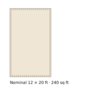
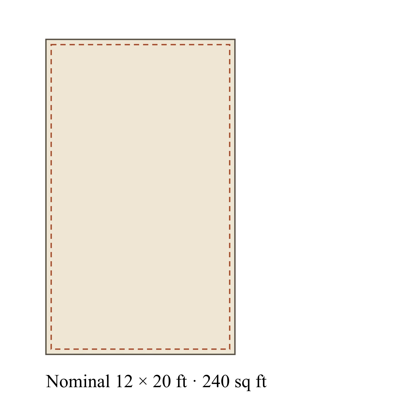
Nominal 12 × 20 ft · 240 sq ft

Solid: nominal footprint definition. Dashed: independently authored interior 136 × 232 in, aligned for illustration. The gap does not specify wall thickness. Usable height: 84 in; opening: 72 × 78 in. Editable planning assumptions.

Compare the reference arrangements

Example layout · 12×20

Permanent machine and assembly zones

A workshop that keeps a saw and assembly table in place between projects.

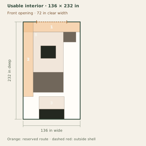
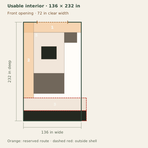
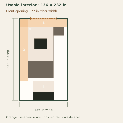
Full-size layout and reserved spacesFull-size footprints with a 24 in entry/side aisle and 30 in bench standing depth. Machine envelopes are reserved simultaneously. Staging is screened along the lengthwise axis; turning, actual machine feed points and manufacturer operating instructions require separate confirmation. Objects outside the outlined shell have not been placed. Numbers refer to the object list. This is a planning diagram, not a construction drawing.Reserved entry cross-aisle: 136 × 24 in at 0, 0 inReserved side aisle: 24 × 178 in at 0, 0 inBench standing area: 60 × 30 in at 38, 178 inWorkbench: 60 × 24 in at 38, 208 inTable saw working envelope: 72 × 96 in at 24, 24 inAssembly table: 72 × 48 in at 24, 120 inTool chest: 30 × 24 in at 96, 24 inTable saw footprint: 36 × 30 in at 42, 57 in12345678Usable interior · 136 × 232 inFront opening · 72 in clear width136 in wide232 in deepOrange: reserved route · dashed red: outside shell

Dark: equipment or storage. Pale areas: activities or zones. Dimensions in inches; scale changes with the view.

  1. 1. Reserved entry cross-aisle: 136 × 24 in
  2. 2. Reserved side aisle: 24 × 178 in
  3. 3. Bench standing area: 60 × 30 in
  4. 4. Workbench: 60 × 24 in
  5. 5. Table saw working envelope: 72 × 96 in
  6. 6. Assembly table: 72 × 48 in
  7. 7. Tool chest: 30 × 24 in
  8. 8. Table saw footprint: 36 × 30 in

Inspect the layout

100%

Dimensions in inches. Zoom changes the view, not your measurements. Select an object to identify its footprint, then swipe or scroll within the drawing. With a keyboard, focus the drawing and use arrow keys.

Input-based planning only. Turning, ramps, thresholds, wall mounting and structural capacity are not approved by this diagram. Escape or Close returns to the page.

The shown arrangement preserves its reserved spaces and entry aisle.

What you gain
Reserves the machine envelope, assembly table, rear bench and entry aisle simultaneously, then checks the entered straight material sweep.
What you give up
The table footprint has no separate all-around assembly working allowance. The small reference material is only 18 in long; longer stock needs a new feed check.
When to choose it
Choose this direction only when your real equipment, operating allowances and material lengths preserve all required zones.

Example interior: 136 × 232 in. Opening: 72 in wide. All reference dimensions and allowances are planning assumptions, not product specifications.

Checks and operating states
  • A failed arrangement is not proof that every layout in this size fails. Only the displayed axis-aligned arrangements were tested.
  • Equipment footprints and reserved spaces are editable planning assumptions. These rectangles do not establish manufacturer operating clearances.
  • Mobile transport tests full-footprint translations along obstacle edges without rotation. Individual workstation approaches and turning remain unassessed. The straight material sweep uses the entered longest material on both sides of the tool and the entered path width. Confirm the actual feed point and manufacturer instructions.
  • Confirm guarding, electrical, dust collection, ventilation, fire separation, loading, and local requirements separately.

Straight material feed at Table saw

Straight material feed at Table sawFull-size footprints with a 24 in entry/side aisle and 30 in bench standing depth. Machine envelopes are reserved simultaneously. Staging is screened along the lengthwise axis; turning, actual machine feed points and manufacturer operating instructions require separate confirmation. Objects outside the outlined shell have not been placed. Numbers refer to the object list. This is a planning diagram, not a construction drawing.Reserved entry cross-aisle: 136 × 24 in at 0, 0 inReserved side aisle: 24 × 178 in at 0, 0 inBench standing area: 60 × 30 in at 38, 178 inWorkbench: 60 × 24 in at 38, 208 inTable saw working envelope: 72 × 96 in at 24, 24 inAssembly table: 72 × 48 in at 24, 120 inTool chest: 30 × 24 in at 96, 24 inTable saw footprint: 36 × 30 in at 42, 57 inTable saw: entered material sweep: 24 × 66 in at 48, 39 in123456789Usable interior · 136 × 232 inFront opening · 72 in clear width136 in wide232 in deepOrange: reserved route · dashed red: outside shell

Dark: equipment or storage. Pale areas: activities or zones. Dimensions in inches; scale changes with the view.

  1. 1. Reserved entry cross-aisle: 136 × 24 in
  2. 2. Reserved side aisle: 24 × 178 in
  3. 3. Bench standing area: 60 × 30 in
  4. 4. Workbench: 60 × 24 in
  5. 5. Table saw working envelope: 72 × 96 in
  6. 6. Assembly table: 72 × 48 in
  7. 7. Tool chest: 30 × 24 in
  8. 8. Table saw footprint: 36 × 30 in
  9. 9. Table saw: entered material sweep: 24 × 66 in

Inspect the layout

100%

Dimensions in inches. Zoom changes the view, not your measurements. Select an object to identify its footprint, then swipe or scroll within the drawing. With a keyboard, focus the drawing and use arrow keys.

Input-based planning only. Turning, ramps, thresholds, wall mounting and structural capacity are not approved by this diagram. Escape or Close returns to the page.

Before buying or building: Measure the assembly task as well as the furniture. Verify feed points, turning, services and equipment instructions with the supplier.
Where this candidate stops working

Only the bench length changes to 148 in, beyond the usable rear wall.

  • Bench standing area exceeds the usable interior in this arrangement.
  • Workbench exceeds the usable interior in this arrangement.
Full-size layout and reserved spacesFull-size footprints with a 24 in entry/side aisle and 30 in bench standing depth. Machine envelopes are reserved simultaneously. Staging is screened along the lengthwise axis; turning, actual machine feed points and manufacturer operating instructions require separate confirmation. Objects outside the outlined shell have not been placed. Numbers refer to the object list. This is a planning diagram, not a construction drawing.Reserved entry cross-aisle: 136 × 24 in at 0, 0 inReserved side aisle: 24 × 178 in at 0, 0 inBench standing area: 148 × 30 in at 0, 178 inWorkbench: 148 × 24 in at 0, 208 inTable saw working envelope: 72 × 96 in at 24, 24 inAssembly table: 72 × 48 in at 24, 120 inTool chest: 30 × 24 in at 96, 24 inTable saw footprint: 36 × 30 in at 42, 57 in12345678Usable interior · 136 × 232 inFront opening · 72 in clear width136 in wide232 in deepOrange: reserved route · dashed red: outside shell

Dark: equipment or storage. Pale areas: activities or zones. Dimensions in inches; scale changes with the view.

  1. 1. Reserved entry cross-aisle: 136 × 24 in
  2. 2. Reserved side aisle: 24 × 178 in
  3. 3. Bench standing area: 148 × 30 in — outside shell
  4. 4. Workbench: 148 × 24 in — outside shell
  5. 5. Table saw working envelope: 72 × 96 in
  6. 6. Assembly table: 72 × 48 in
  7. 7. Tool chest: 30 × 24 in
  8. 8. Table saw footprint: 36 × 30 in

Worked example · not a measured product or customer story

Mower, two bikes and a shelf compete for the same exits

The example retains the 54 × 84 in mower, two 28 × 72 in floor-parked bikes and an 18 × 72 in shelf. Every required route is checked with the other parked objects present. Extra floor area is not an independent-access guarantee.

12×20 example

This layout needs a change

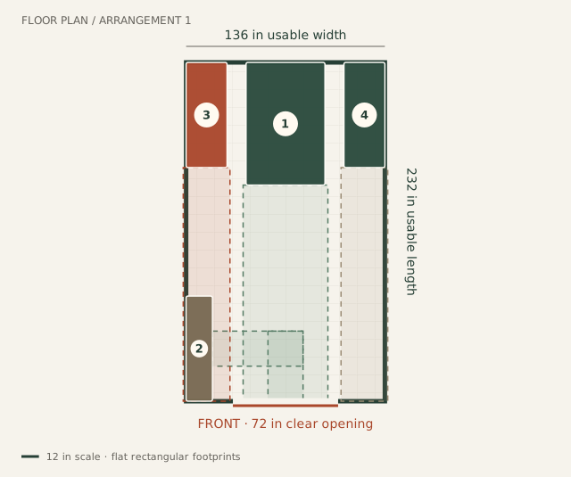
Storage layout from the current inputsNumbers identify objects in the list below. Dashed shaded regions are selected retrieval paths, not structural or turning checks.FLOOR PLAN / ARRANGEMENT 1136 in usable width232 in usable lengthRiding mower · 54 in × 84 in1Storage shelf · 18 in × 72 in2Bikes 1 · 28 in × 72 in3Bikes 2 · 28 in × 72 in4FRONT · 72 in clear opening12 in scale · flat rectangular footprints
  1. 1. Riding mower
  2. 2. Storage shelf
  3. 3. Bikes 1
  4. 4. Bikes 2

Numbers identify the objects in this legend. Dashed regions show the paths actually checked. Turning, ramps, thresholds and structural capacity are not assessed.

Inspect the layout

100%

Zoom in, then swipe or scroll within the drawing. With a keyboard, focus the drawing and use arrow keys. Zoom changes the view, not your measurements.

  1. 1. Riding mower
  2. 2. Storage shelf
  3. 3. Bikes 1
  4. 4. Bikes 2

Input-based planning only. Turning, ramps, thresholds, wall mounting and structural capacity are not approved by this diagram. Escape or Close returns to the page.

Usable interior: 136 × 232 × 84 in. Clear opening: 72 × 78 in; centered by assumption.

  • Needs a change: Bikes 1: straight retrieval. The selected straight path is blocked by Storage shelf.
  • Not assessed: Bikes 2: straight retrieval. This position needs a turn or more opening measurements; straight retrieval has not been established.
All evaluated checks (22)
  • Pass with these inputs: Riding mower: clear door width. 54 in width + 2 in each side; 72 in clear opening.
  • Pass with these inputs: Riding mower: clear door height. 48 in item height; 78 in clear opening. No tilt is modeled.
  • Pass with these inputs: Riding mower: interior height. 48 in overall height; 84 in stated usable height. This does not test lifting or overhead working space.
  • Pass with these inputs: Storage shelf: clear door width. 18 in width + 2 in each side; 72 in clear opening.
  • Pass with these inputs: Storage shelf: clear door height. 72 in item height; 78 in clear opening. No tilt is modeled.
  • Pass with these inputs: Storage shelf: interior height. 72 in overall height; 84 in stated usable height. This does not test lifting or overhead working space.
  • Pass with these inputs: Bikes: clear door width. 28 in width + 2 in each side; 72 in clear opening.
  • Pass with these inputs: Bikes: clear door height. 44 in item height; 78 in clear opening. No tilt is modeled.
  • Pass with these inputs: Bikes: interior height. 44 in overall height; 84 in stated usable height. This does not test lifting or overhead working space.
  • Pass with these inputs: Bikes: clear door width. 28 in width + 2 in each side; 72 in clear opening.
  • Pass with these inputs: Bikes: clear door height. 44 in item height; 78 in clear opening. No tilt is modeled.
  • Pass with these inputs: Bikes: interior height. 44 in overall height; 84 in stated usable height. This does not test lifting or overhead working space.
  • Pass with these inputs: Riding mower: floor boundary. The complete footprint is within the stated interior.
  • Pass with these inputs: Storage shelf: floor boundary. The complete footprint is within the stated interior.
  • Pass with these inputs: Storage shelf: wall preference. You chose the left wall.
  • Pass with these inputs: Bikes 1: floor boundary. The complete footprint is within the stated interior.
  • Pass with these inputs: Bikes 2: floor boundary. The complete footprint is within the stated interior.
  • Pass with these inputs: Clear opening position. The opening is within the stated front wall.
  • Pass with these inputs: Riding mower: straight retrieval. The stated straight sweep to the clear opening contains no other floor object. Turning, thresholds and ramps are not checked.
  • Pass with these inputs: Storage shelf: walking approach. The selected 24 in walking aisle reaches this shelf/work surface without crossing a floor object. Reach, assembly and load capacity are not assessed.
  • Needs a change: Bikes 1: straight retrieval. The selected straight path is blocked by Storage shelf.
  • Not assessed: Bikes 2: straight retrieval. This position needs a turn or more opening measurements; straight retrieval has not been established.

No distinct fully checked rearrangement was found in the limited search. This does not prove all arrangements impossible.

Inspect every input and its source

All dimensions and positions are authored planning assumptions. Door side allowance: 2 in; walking aisle: 24 in. No manufacturer specification or user measurement is implied.

  • 1 × Riding mower: 54 × 84 × 48 in; frequent access; floor; roll; 0° parked orientation.
  • 1 × Storage shelf: 18 × 72 × 72 in; occasional access; shelf; fixed; 0° parked orientation.
  • 2 × Bikes: 28 × 72 × 44 in; frequent access; floor; roll; 0° parked orientation.

Case: mower-bikes · authored-cases-2026-09-03. Diagram and checks: storage-fit-1. Positions chosen by the limited automatic search.

Continue my saved project

Reading this example does not change your project. Copying asks before replacing it. Planning only: not a structural, installation, delivery or permit approval.

Same arrangement: 12×20 and 12×16

Equipment, activities and allowances are identical. The authored shell dimensions and opening can differ. The drawings use one scale, including full-size items that cannot be placed. Positions can change as the bounded layout search uses the available space.

12×20

Example interior 136 × 232 in; clear door 72 × 78 in.

Full-size layout and reserved spacesFull-size footprints with a 24 in entry/side aisle and 30 in bench standing depth. Machine envelopes are reserved simultaneously. Staging is screened along the lengthwise axis; turning, actual machine feed points and manufacturer operating instructions require separate confirmation. Objects outside the outlined shell have not been placed. Numbers refer to the object list. This is a planning diagram, not a construction drawing.Reserved entry cross-aisle: 136 × 24 in at 0, 0 inReserved side aisle: 24 × 178 in at 0, 0 inBench standing area: 60 × 30 in at 38, 178 inWorkbench: 60 × 24 in at 38, 208 inTable saw working envelope: 72 × 96 in at 24, 24 inAssembly table: 72 × 48 in at 24, 120 inTool chest: 30 × 24 in at 96, 24 inTable saw footprint: 36 × 30 in at 42, 57 in12345678Usable interior · 136 × 232 inFront opening · 72 in clear width136 in wide232 in deepOrange: reserved route · dashed red: outside shell

Dark: equipment or storage. Pale areas: activities or zones. Dimensions in inches; scale changes with the view.

  1. 1. Reserved entry cross-aisle: 136 × 24 in
  2. 2. Reserved side aisle: 24 × 178 in
  3. 3. Bench standing area: 60 × 30 in
  4. 4. Workbench: 60 × 24 in
  5. 5. Table saw working envelope: 72 × 96 in
  6. 6. Assembly table: 72 × 48 in
  7. 7. Tool chest: 30 × 24 in
  8. 8. Table saw footprint: 36 × 30 in

Inspect the layout

100%

Dimensions in inches. Zoom changes the view, not your measurements. Select an object to identify its footprint, then swipe or scroll within the drawing. With a keyboard, focus the drawing and use arrow keys.

Input-based planning only. Turning, ramps, thresholds, wall mounting and structural capacity are not approved by this diagram. Escape or Close returns to the page.

The shown arrangement preserves its reserved spaces and entry aisle.

  • A failed arrangement is not proof that every layout in this size fails. Only the displayed axis-aligned arrangements were tested.
  • Equipment footprints and reserved spaces are editable planning assumptions. These rectangles do not establish manufacturer operating clearances.
12×16

Example interior 136 × 184 in; clear door 72 × 78 in.

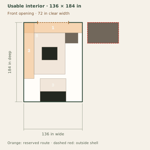
Full-size layout and reserved spacesFull-size footprints with a 24 in entry/side aisle and 30 in bench standing depth. Machine envelopes are reserved simultaneously. Staging is screened along the lengthwise axis; turning, actual machine feed points and manufacturer operating instructions require separate confirmation. Objects outside the outlined shell have not been placed. Numbers refer to the object list. This is a planning diagram, not a construction drawing.Reserved entry cross-aisle: 136 × 24 in at 0, 0 inReserved side aisle: 24 × 130 in at 0, 0 inBench standing area: 60 × 30 in at 38, 130 inWorkbench: 60 × 24 in at 38, 160 inTable saw working envelope: 72 × 96 in at 24, 24 inTool chest: 30 × 24 in at 96, 24 inAssembly table: 72 × 48 in at 148, 0 inTable saw footprint: 36 × 30 in at 42, 57 in12345678Usable interior · 136 × 184 inFront opening · 72 in clear width136 in wide184 in deepOrange: reserved route · dashed red: outside shell

Dark: equipment or storage. Pale areas: activities or zones. Dimensions in inches; scale changes with the view.

  1. 1. Reserved entry cross-aisle: 136 × 24 in
  2. 2. Reserved side aisle: 24 × 130 in
  3. 3. Bench standing area: 60 × 30 in
  4. 4. Workbench: 60 × 24 in
  5. 5. Table saw working envelope: 72 × 96 in
  6. 6. Tool chest: 30 × 24 in
  7. 7. Assembly table: 72 × 48 in — outside shell
  8. 8. Table saw footprint: 36 × 30 in

Inspect the layout

100%

Dimensions in inches. Zoom changes the view, not your measurements. Select an object to identify its footprint, then swipe or scroll within the drawing. With a keyboard, focus the drawing and use arrow keys.

Input-based planning only. Turning, ramps, thresholds, wall mounting and structural capacity are not approved by this diagram. Escape or Close returns to the page.

This tested arrangement has unresolved geometry conflicts.

  • Assembly table: no non-overlapping position was found in this bounded arrangement search.

Moving from the first example to the second changes usable width by 0 in, depth by -48 in and clear door width by 0 in. These differences belong to these examples. Obtain actual product measurements before choosing.

A changed result applies to the shown arrangement only. A different layout may work; a larger candidate can still fail a doorway, site or budget check.

Download the authored reference diagrams

Version 2026-09-08-decisions. These files reproduce the public examples, including failed arrangements. Your private measurements are only included when you generate your own brief.

  • Figure 1 · 12×20 shellSVGWebP
  • Figure 2 · workshop permanent layoutSVGWebP
  • Figure 3 · greenhouse separated layoutSVGWebP
  • Figure 4 · 12×20 boundarySVGWebP
  • Figure 5 · mower bikes shell 12×20 referenceSVGWebP
  • Figure 6 · 12×20 12×16 workshop permanent 12×20SVGWebP
  • Figure 7 · 12×20 12×16 workshop permanent 12×16SVGWebP

Change this project?