Shed use · planning scenario

Home gym shed: equipment first, then shell

Compare open training space with an equipment-led layout. Check the shown floor arrangement and the entered equipment or movement heights.

Live planner · Editable reference layouts · No account needed

Compare the arrangements

Start with the task, then test the space.

Choose floor space and usable height together. Equipment footprints, an open activity zone and overhead movement are separate requirements.

Use the open-training layout if floor activity matters most. Use the rack-and-bench layout to test equipment plus its height requirements.

Start with a useful arrangement

Ways to use the space.

Compare what each layout makes room for and what it leaves out. These are dimensioned planning layouts you can adapt, with dimensions and assumptions shown before you enter anything.

Example layout · 10×12

Open space for floor training

Mobility, stretching and floor-based sessions that need an uncluttered area.

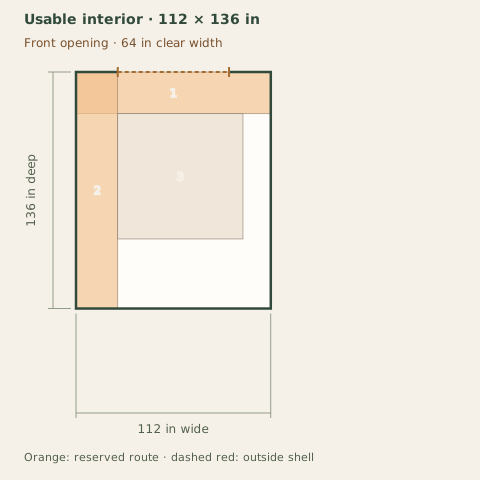
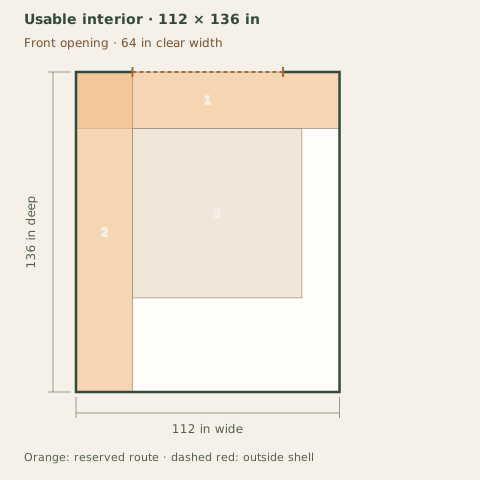
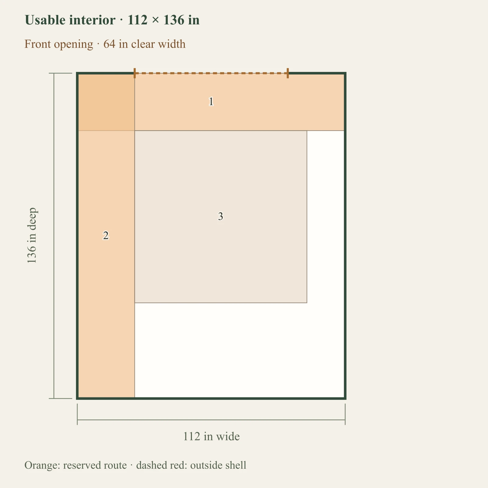
Full-size layout and reserved spacesSeparate full-size equipment envelopes (6 in on each side), open training area and a 24 in frequent access path. Access frequency does not reduce physical dimensions. Vertical requirement: 70 in; usable height: 84 in. Objects outside the outlined shell have not been placed. Numbers refer to the object list. This is a planning diagram, not a construction drawing.Reserved entry cross-aisle: 112 × 24 in at 0, 0 inReserved side aisle: 24 × 136 in at 0, 0 inOpen training zone: 72 × 72 in at 24, 24 in123Usable interior · 112 × 136 inFront opening · 64 in clear width112 in wide136 in deepOrange: reserved route · dashed red: outside shell

Dark: equipment or storage. Pale areas: activities or zones. Dimensions in inches; scale changes with the view.

  1. 1. Reserved entry cross-aisle: 112 × 24 in
  2. 2. Reserved side aisle: 24 × 136 in
  3. 3. Open training zone: 72 × 72 in

Inspect the layout

100%

Dimensions in inches. Zoom changes the view, not your measurements. Select an object to identify its footprint, then swipe or scroll within the drawing. With a keyboard, focus the drawing and use arrow keys.

Input-based planning only. Turning, ramps, thresholds, wall mounting and structural capacity are not approved by this diagram. Escape or Close returns to the page.

The shown arrangement preserves its reserved spaces and entry aisle.

What you gain
Reserves the entered open training zone separately from the entry aisle.
What you give up
No fixed cardio machine or rack is included. Adding one reduces the same usable floor.
When to choose it
Choose this direction when open movement space is the priority.

Example interior: 112 × 136 in. Opening: 64 in wide. All reference dimensions and allowances are planning assumptions, not product specifications.

Checks and operating states
  • A failed arrangement is not proof that every layout in this size fails. Only the displayed axis-aligned arrangements were tested.
  • The entered separation is an assumption, not an equipment-specific safety clearance. Individual equipment approaches and delivery through the doorway remain unassessed.
  • Structural floor capacity, impact or drop loads, rack anchoring, electrical work, HVAC, and equipment safety remain unassessed.
  • Replace example footprints and movement allowances with equipment instructions and your measurements.

Before buying or building: Measure the movements you intend to make; confirm surface, climate, ventilation and local requirements separately.
Example layout · 12×16

A rack-and-bench training space

Training organized around a rack and a separate bench footprint.

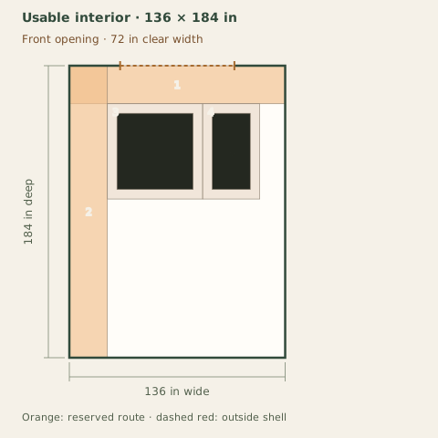
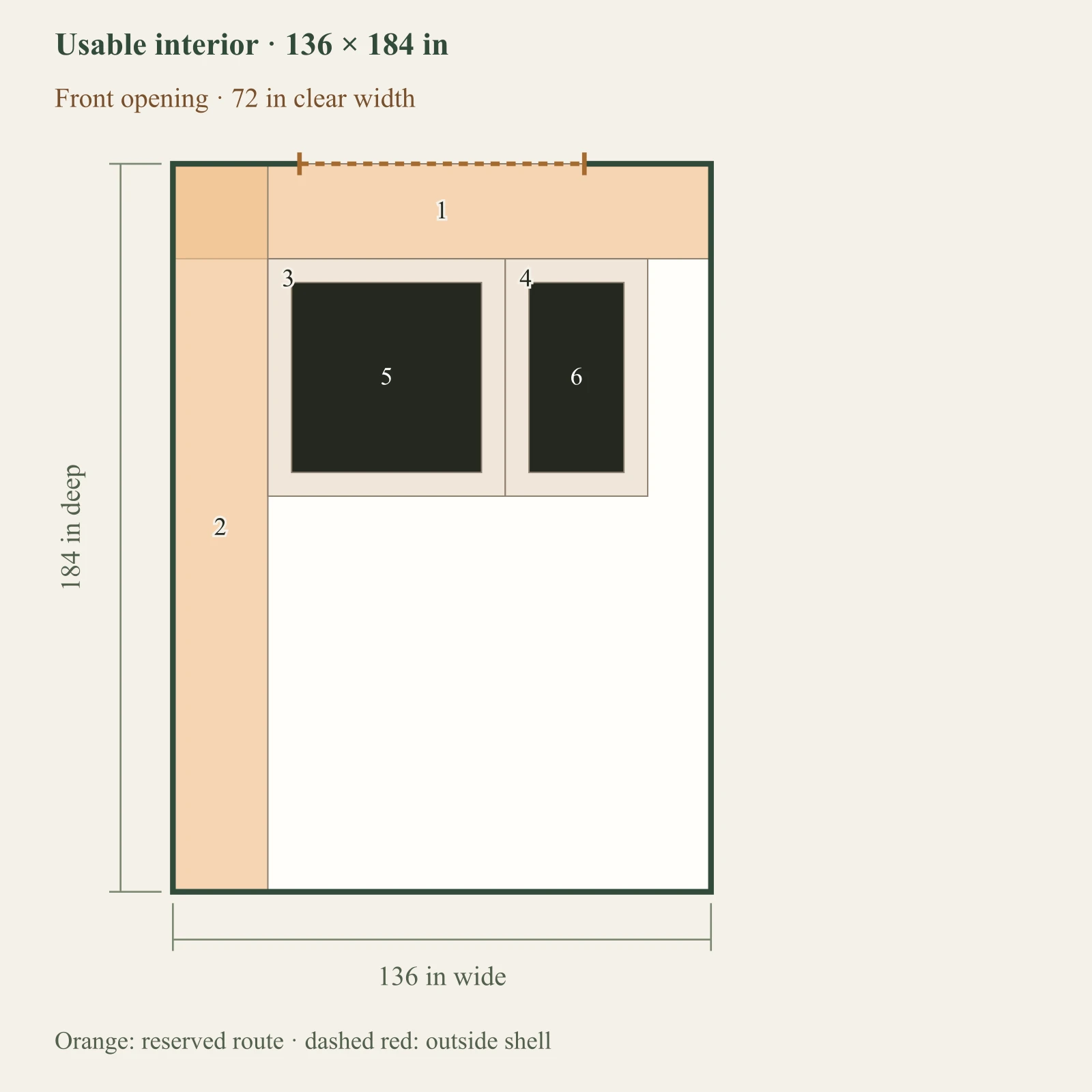
Full-size layout and reserved spacesSeparate full-size equipment envelopes (6 in on each side), open training area and a 24 in frequent access path. Access frequency does not reduce physical dimensions. Vertical requirement: 84 in; usable height: 84 in. Objects outside the outlined shell have not been placed. Numbers refer to the object list. This is a planning diagram, not a construction drawing.Reserved entry cross-aisle: 136 × 24 in at 0, 0 inReserved side aisle: 24 × 184 in at 0, 0 inRack with separation: 60 × 60 in at 24, 24 inBench with separation: 36 × 60 in at 84, 24 inRack: 48 × 48 in at 30, 30 inBench: 24 × 48 in at 90, 30 in123456Usable interior · 136 × 184 inFront opening · 72 in clear width136 in wide184 in deepOrange: reserved route · dashed red: outside shell

Dark: equipment or storage. Pale areas: activities or zones. Dimensions in inches; scale changes with the view.

  1. 1. Reserved entry cross-aisle: 136 × 24 in
  2. 2. Reserved side aisle: 24 × 184 in
  3. 3. Rack with separation: 60 × 60 in
  4. 4. Bench with separation: 36 × 60 in
  5. 5. Rack: 48 × 48 in
  6. 6. Bench: 24 × 48 in

Inspect the layout

100%

Dimensions in inches. Zoom changes the view, not your measurements. Select an object to identify its footprint, then swipe or scroll within the drawing. With a keyboard, focus the drawing and use arrow keys.

Input-based planning only. Turning, ramps, thresholds, wall mounting and structural capacity are not approved by this diagram. Escape or Close returns to the page.

The shown arrangement preserves its reserved spaces and entry aisle.

What you gain
Reserves each equipment envelope and screens rack height independently from floor fit.
What you give up
The separate bench footprint is conservative; using it inside a rack needs an equipment-specific arrangement.
When to choose it
Choose this direction when permanently positioned equipment matters more than a large open zone.

Example interior: 136 × 184 in. Opening: 72 in wide. All reference dimensions and allowances are planning assumptions, not product specifications.

Checks and operating states
  • A failed arrangement is not proof that every layout in this size fails. Only the displayed axis-aligned arrangements were tested.
  • The entered separation is an assumption, not an equipment-specific safety clearance. Individual equipment approaches and delivery through the doorway remain unassessed.
  • Structural floor capacity, impact or drop loads, rack anchoring, electrical work, HVAC, and equipment safety remain unassessed.
  • Replace example footprints and movement allowances with equipment instructions and your measurements.

Before buying or building: Take the equipment manuals and intended use to your supplier. Floor capacity, anchoring and equipment safety need separate review.

What changes when the same arrangement gets smaller?

These results keep the first reference's equipment, activities and allowances unchanged. Each shell has its own disclosed interior and door assumptions. All three drawings use the same scale. A failed arrangement does not prove every layout impossible.

8×10

Interior 88 × 112 in; door 48 in.

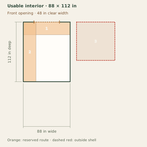
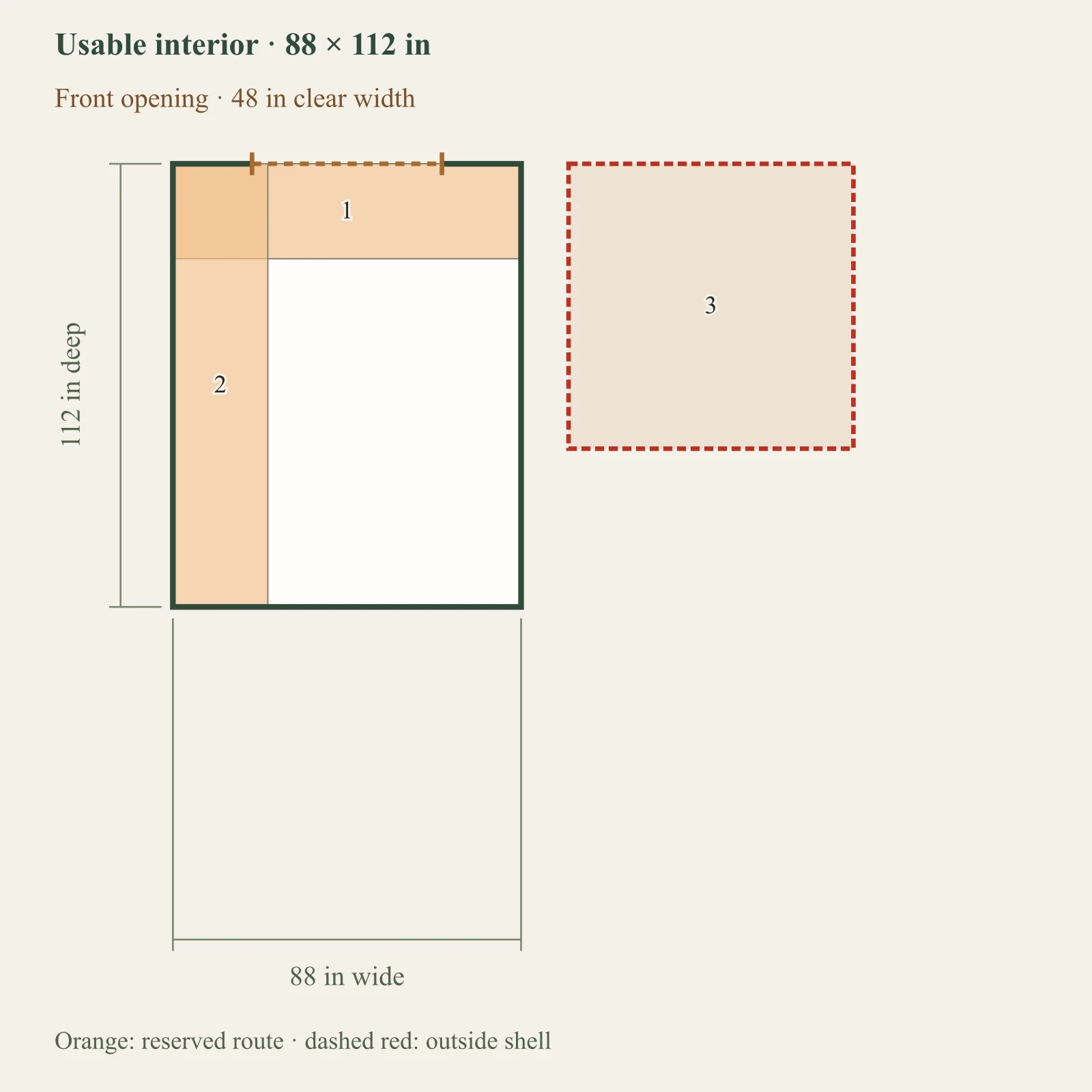
Full-size layout and reserved spacesSeparate full-size equipment envelopes (6 in on each side), open training area and a 24 in frequent access path. Access frequency does not reduce physical dimensions. Vertical requirement: 70 in; usable height: 78 in. Objects outside the outlined shell have not been placed. Numbers refer to the object list. This is a planning diagram, not a construction drawing.Reserved entry cross-aisle: 88 × 24 in at 0, 0 inReserved side aisle: 24 × 112 in at 0, 0 inOpen training zone: 72 × 72 in at 100, 0 in123Usable interior · 88 × 112 inFront opening · 48 in clear width88 in wide112 in deepOrange: reserved route · dashed red: outside shell
Object dimensions & enlarged view

Inspect the layout

100%

Dimensions in inches. Zoom changes the view, not your measurements. Select an object to identify its footprint, then swipe or scroll within the drawing. With a keyboard, focus the drawing and use arrow keys.

Input-based planning only. Turning, ramps, thresholds, wall mounting and structural capacity are not approved by this diagram. Escape or Close returns to the page.

  • 1. Reserved entry cross-aisle: 88 × 24 in
  • 2. Reserved side aisle: 24 × 112 in
  • 3. Open training zone: 72 × 72 in

Revise this arrangement

Open training zone: no non-overlapping position was found in this bounded arrangement search.

10×12

Interior 112 × 136 in; door 64 in.

Full-size layout and reserved spacesSeparate full-size equipment envelopes (6 in on each side), open training area and a 24 in frequent access path. Access frequency does not reduce physical dimensions. Vertical requirement: 70 in; usable height: 84 in. Objects outside the outlined shell have not been placed. Numbers refer to the object list. This is a planning diagram, not a construction drawing.Reserved entry cross-aisle: 112 × 24 in at 0, 0 inReserved side aisle: 24 × 136 in at 0, 0 inOpen training zone: 72 × 72 in at 24, 24 in123Usable interior · 112 × 136 inFront opening · 64 in clear width112 in wide136 in deepOrange: reserved route · dashed red: outside shell
Object dimensions & enlarged view

Inspect the layout

100%

Dimensions in inches. Zoom changes the view, not your measurements. Select an object to identify its footprint, then swipe or scroll within the drawing. With a keyboard, focus the drawing and use arrow keys.

Input-based planning only. Turning, ramps, thresholds, wall mounting and structural capacity are not approved by this diagram. Escape or Close returns to the page.

  • 1. Reserved entry cross-aisle: 112 × 24 in
  • 2. Reserved side aisle: 24 × 136 in
  • 3. Open training zone: 72 × 72 in

Shown geometry passes

A failed arrangement is not proof that every layout in this size fails. Only the displayed axis-aligned arrangements were tested.

12×16

Interior 136 × 184 in; door 72 in.

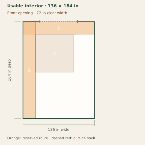
Full-size layout and reserved spacesSeparate full-size equipment envelopes (6 in on each side), open training area and a 24 in frequent access path. Access frequency does not reduce physical dimensions. Vertical requirement: 70 in; usable height: 84 in. Objects outside the outlined shell have not been placed. Numbers refer to the object list. This is a planning diagram, not a construction drawing.Reserved entry cross-aisle: 136 × 24 in at 0, 0 inReserved side aisle: 24 × 184 in at 0, 0 inOpen training zone: 72 × 72 in at 24, 24 in123Usable interior · 136 × 184 inFront opening · 72 in clear width136 in wide184 in deepOrange: reserved route · dashed red: outside shell
Object dimensions & enlarged view

Inspect the layout

100%

Dimensions in inches. Zoom changes the view, not your measurements. Select an object to identify its footprint, then swipe or scroll within the drawing. With a keyboard, focus the drawing and use arrow keys.

Input-based planning only. Turning, ramps, thresholds, wall mounting and structural capacity are not approved by this diagram. Escape or Close returns to the page.

  • 1. Reserved entry cross-aisle: 136 × 24 in
  • 2. Reserved side aisle: 24 × 184 in
  • 3. Open training zone: 72 × 72 in

Shown geometry passes

A failed arrangement is not proof that every layout in this size fails. Only the displayed axis-aligned arrangements were tested.

Change one measurement

Find the condition that changes the answer.

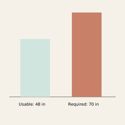
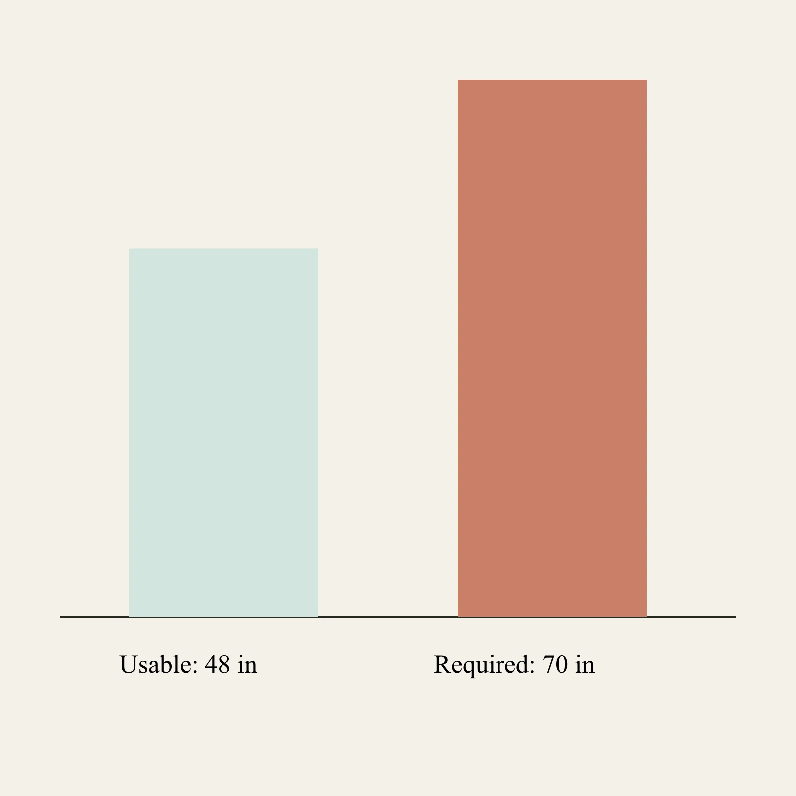
Start with a deliberately failing example, then restore the reference or try your own value. Only usable interior height changes; the other equipment, allowances and shed dimensions stay fixed.

This experiment is separate from your saved project. Its inputs are planning assumptions, not a product specification or a universal threshold.

This tested arrangement has unresolved geometry conflicts.

  • The 70 in vertical requirement exceeds the entered 48 in usable height.

Floor space cannot resolve a height conflict. Confirm usable height at the actual equipment or activity location.

Usable: 48 inRequired: 70 in
Height conflict: the 70 in entered requirement exceeds 48 in usable height. Standing height, selected equipment, treadmill deck and entered overhead movement are screened separately from floor placement. This is not an equipment safety clearance.
See how to measure and revise this requirement

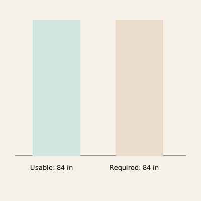
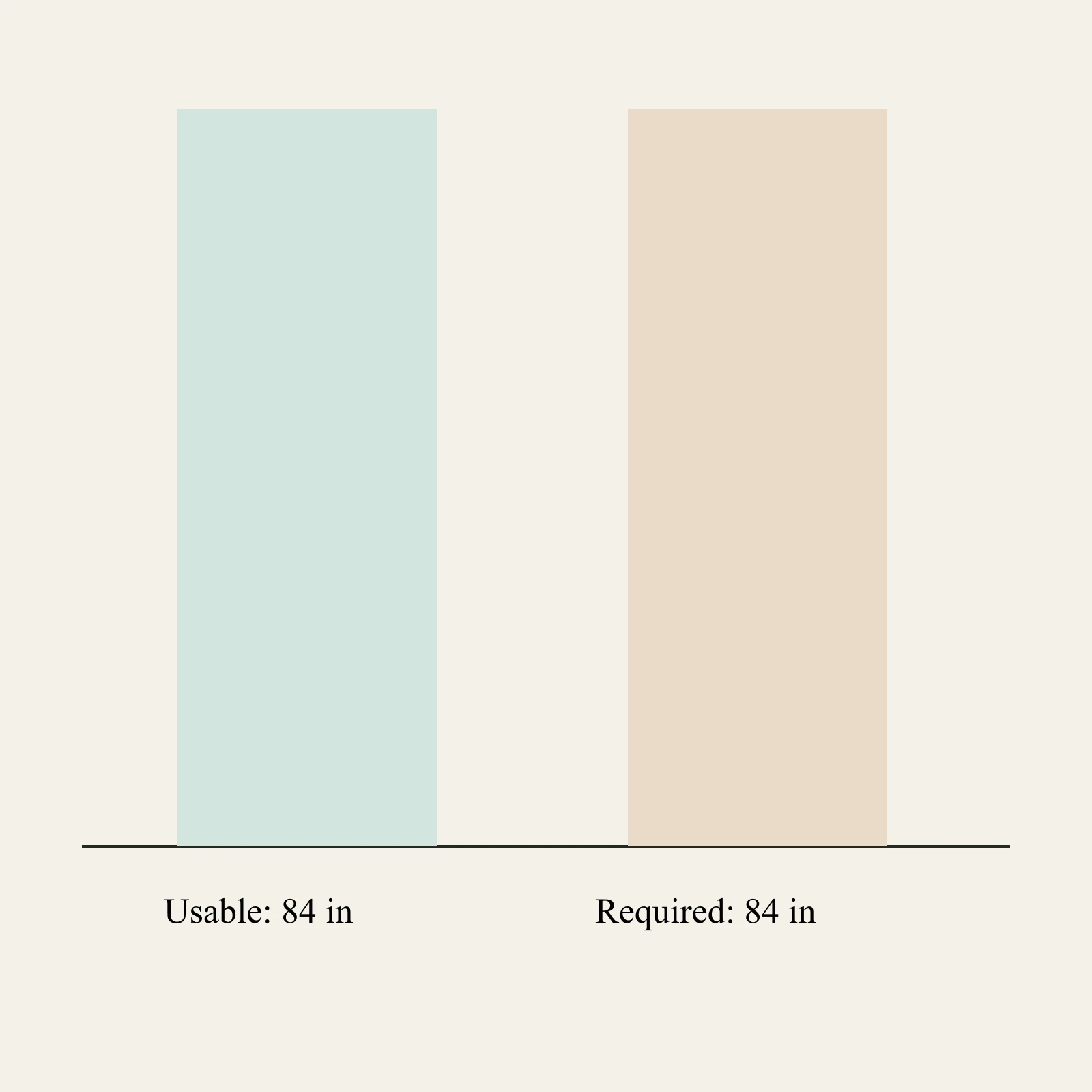
Floor fit can pass while height fails.

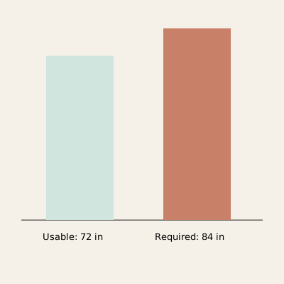
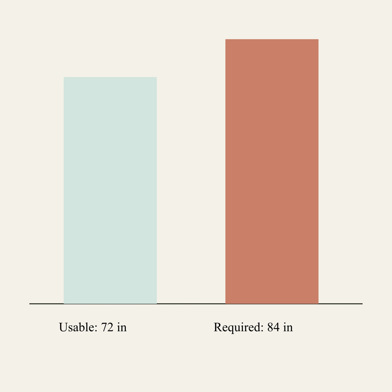
The same rack-and-bench reference is shown with its example usable height and a deliberately lower 72 in ceiling.

Usable: 84 inRequired: 84 in
The 84 in entered requirement is within 84 in usable height. Standing height, selected equipment, treadmill deck and entered overhead movement are screened separately from floor placement. This is not an equipment safety clearance.
Usable: 72 inRequired: 84 in
Height conflict: the 84 in entered requirement exceeds 72 in usable height. Standing height, selected equipment, treadmill deck and entered overhead movement are screened separately from floor placement. This is not an equipment safety clearance.
Download the authored reference diagrams

Version 2026-09-08-decisions. These files reproduce the public examples, including failed arrangements. Your private measurements are only included when you generate your own brief.

  • Figure 1 · gym open layoutSVGWebP
  • Figure 2 · gym equipment layoutSVGWebP
  • Figure 3 · gym open 8×10 comparisonSVGWebP
  • Figure 4 · gym open 10×12 comparisonSVGWebP
  • Figure 5 · gym open 12×16 comparisonSVGWebP
  • Figure 6 · gym open boundarySVGWebP
  • Figure 7 · gym height sectionSVGWebP
  • Figure 8 · gym height failureSVGWebP

From an example to your measurements

Measure what can change the answer.

Work through these checks before copying a reference into your project. The example allowances are editable planning choices, not universal safety requirements.

01

Equipment in use

How to measure

Measure each assembled item with its moving parts extended. Enter the open training area you actually need, rather than treating the leftover area as an exercise zone.

What it changes

The model keeps equipment, the protected entrance route and selected activity area visible as separate rectangles.

If the check fails

Remove an optional item, revise its measured envelope, or compare a usable interior that separates the activities. Never shrink equipment dimensions just to obtain a pass.

02

Height at the activity location

How to measure

Record the lowest usable height over the intended rack or activity, including beams or sloping roof areas. Obtain equipment height and your required movement height separately.

What it changes

A plan view can pass while a rack, treadmill user or overhead movement fails the height check. The model uses the height you enter; it does not map a whole roof profile.

If the check fails

Check a different equipment location or a product with sufficient confirmed usable height. More floor area by itself does not resolve a vertical conflict.

03

Access and installation

How to measure

Measure the real opening and equipment delivery dimensions. Distinguish assembled use from how the equipment will be brought inside.

What it changes

The floor arrangement is not a delivery, loading or installation approval.

If the check fails

Confirm assembly access, floor loading, anchoring, ventilation and electrical needs with the equipment and shed suppliers before treating the candidate as ready to buy.

Your next step

Put your measurements to work.

Choose a reference above to start from its exact layout, or continue with the dimensions already in your browser project. The workbench connects equipment, candidate sizes, yard and quote checks to one planning brief.

  • Enter the exact equipment footprint and manufacturer-required clearances.
  • Confirm interior height, floor loading, electrical and ventilation for your equipment.
  • Keep emergency and door egress clear.
Review my saved brief

Example layouts stay separate until you adopt one. Changing the active task keeps existing measurements and asks you to review the previous candidate decisions.

Questions to carry into my project

Decision questions

  1. 01Which equipment has a permanent floor footprint?
  2. 02How much open exercise area is required?
  3. 03Does usable interior height fit the rack and user movement?
  4. 04Does the equipment arrangement leave a clear entry route?
  5. 05Which safety and structural questions need separate verification?

Change this project?